Deep fryer with rotatable frying cage
A deep fryer and frying cage technology, which is applied to utensils for frying things in oil, oil/fat baking, household appliances, etc., can solve the problems of inconvenient cleaning, pollution, expansion, etc., to improve work efficiency, solve The taste is different and the effect of saving oil consumption
- Summary
- Abstract
- Description
- Claims
- Application Information
AI Technical Summary
Problems solved by technology
Method used
Image
Examples
Embodiment 1
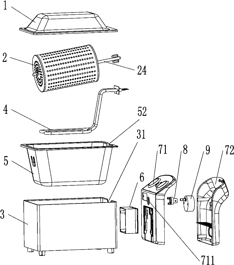
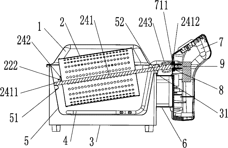
[0034] Such as Figure 1 to Figure 6 As shown, the deep fryer of this embodiment includes a loam cake 1, a frying basket 2, a shell 3, a heater 4 and an inner pot 5, the inner pot 5 is placed in the shell 3, and the heater 4 is an electric heating tube placed in the inner pot 5 The inner bottom (the outer bottom is also available), and the fried basket 2 is detachably placed in the inner pot 5. The control box 7 connected to the heater 4 is formed by fastening the control box cover 71 and the control box seat 72, and is fixed on the side of the shell 3 through the support seat 6. The control box 7 is fixed with a coupler 8, a motor 9 and a thermostat Electrical controls such as switches and timers (not shown in the figure).
[0035] In order to facilitate the dumping of the cooking oil in the inner pot 5 and the cleaning of the inner pot 5, the inner pot 5 and the outer shell 3 are designed to be detachable and fixed, and the upper edge of the inner pot 5 is provided with a h...
Embodiment 2
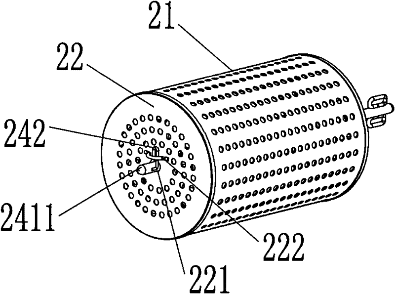
[0045] Different from Embodiment 1, the front end portion 2411 of the rotating shaft in this embodiment is cylindrical, and the other parts are quadrangular prisms, such as Figure 7 As shown, of course, other non-cylindrical shapes, such as D-shaped columns, can also be designed.
[0046] Correspondingly, the first assembly hole 221 on the front cover 22 of the fried basket and the second assembly hole 231 on the rear cover 23 are all square holes that are clearance-fitted with the quadrangular prism. Interference limit is formed in the direction of rotation of 241 to ensure that the fried basket 2 rotates with the rotating shaft 241. At the same time, the step 244 formed between the cylindrical front end 2411 of the rotating shaft 241 and the square prism is interfered and limited on the horizontal axis of the rotating shaft to avoid The rotating shaft is detached from the fried cage 2; correspondingly, the groove 82 for accommodating the rear end 2412 of the rotating shaft ...
Embodiment 3
[0049] The difference between this embodiment and Embodiment 1 is that the shaft assembly 24 includes a first shaft assembly 245 and a second shaft assembly 246, one end of the first shaft assembly 245 is welded and fixed with the fryer cage front cover 22 or designed integrally, and the other end is movable. On the inner pot step 51; one end of the second shaft assembly 246 is welded and fixed or integrated with the rear cover 23 of the fried basket, and the other end is limitedly coupled with the coupler 8, such as Figure 8 shown. Other structures are the same as those in Embodiment 1, and will not be described in detail again.
PUM
 Abstract
Description
Claims
Application Information
 - R&D
- Intellectual Property
- Life Sciences
- Materials
- Tech Scout
- Unparalleled Data Quality
- Higher Quality Content
- 60% Fewer Hallucinations
Browse by: Latest US Patents, China's latest patents, Technical Efficacy Thesaurus, Application Domain, Technology Topic, Popular Technical Reports.
© 2025 PatSnap. All rights reserved.Legal|Privacy policy|Modern Slavery Act Transparency Statement|Sitemap|About US| Contact US: help@patsnap.com


