
Method and device for controlling quadrature voltage based on IQ electro-optical modulator

An electro-optical modulator and control method technology, which is applied in the field of communication, can solve the problems of large package size, not too large amplitude attenuation, and increased package cost of the modulator, so as to achieve the effect of reducing package cost and improving reliability

Inactive Publication Date: 2017-03-29
GUANGXUN SCI & TECH WUHAN
View PDF5 Cites 11 Cited by
  • Summary
  • Abstract
  • Description
  • Claims
  • Application Information

AI Technical Summary

Problems solved by technology

OIF 100G lithium niobate and InP coherent modulator standards clearly stipulate the MPD bandwidth of the modulator, and the requirement is not lower than 1GHz. 2. The control of the quadrature voltage is realized by monitoring the amplitude of the 32G baud rate QPSK optical signal through the MPD. It is necessary to ensure that the amplitude attenuation of the high-speed optical signal cannot be too large after entering the MPD. Therefore, this control scheme has higher requirements on the bandwidth of the MPD.
However, the high-frequency packaging of the modulator MPD will greatly increase the packaging cost of the modulator, and the corresponding tube case and high-frequency ceramic board need to be carefully designed, and the package size is large.

Method used


Image

  • Method and device for controlling quadrature voltage based on IQ electro-optical modulator
  • Method and device for controlling quadrature voltage based on IQ electro-optical modulator
  • Method and device for controlling quadrature voltage based on IQ electro-optical modulator

Examples


Embodiment Construction

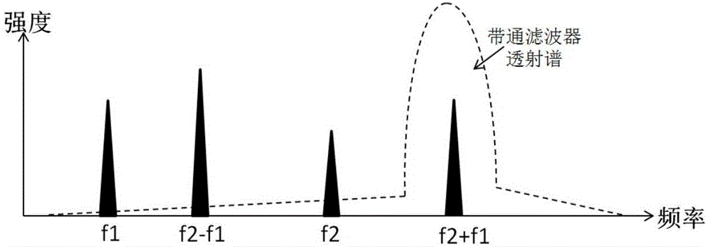
[0032] The automatic control method of the quadrature voltage of the IQ electro-optic modulator based on the low-speed MPD in the invention is described in detail below in conjunction with the embodiments and accompanying drawings. In the embodiment, a parallel MZI type silicon photonic IQ modulator is used, wherein the modulator The bandwidth of the MPD is 300MHz, which belongs to the low-speed MPD and does not meet the requirement that the bandwidth of the MPD should be greater than 1GHz in the OIF standard, but the performance index of the modulator can meet the requirements of the OIF standard through the automatic control method provided by the present invention.

[0033]The invention provides an automatic bias voltage control device of a parallel MZI type IQ electro-optic modulator, such as Figure 4 Shown, including IQ electro-optic modulator and feedback control circuit. Among them, the IQ electro-optic modulator adopts a double-parallel Mach-Zehnder interferometer (Ma...


PUM


Abstract

The invention discloses a method and device for controlling quadrature voltage based on an IQ electro-optical modulator. The IQ electro-optical modulator adopts a double parallel Mach-Zehnder interferometer, and the method comprises the following steps of: enabling an I sub-modulator and a Q sub-modulator to output two paths of BPSK optical signal orthogonal waves, and modulating to QPSK optical signals; respectively overlapping small periodic disturbance of which the frequency is f1 and f2 on the optimum bias voltages of the I sub-modulator and the Q sub-modulator, wherein f1 is not equal to f2; obtaining low-speed AC small signals generated by the IQ electro-optical modulator under the small periodic disturbance and extracting f1+f2 sum frequency components in the small signals through a monitoring photodiode (MPD); overlapping small disturbance on the bias voltage of a pi / 2 phase modulation electrode, and extracting the feedback waveform of the f1+f2 sum frequency components; and judging the amplitude and phase of the feedback waveform of the f1+f2 sum frequency components to adjust the bias voltage applied to the pi / 2 phase modulation electrode. The method and device disclosed by the invention only adopt low-frequency package, and thus the reliability of the IQ electro-optical modulator can be increased, and the package cost can be reduced.

Description

technical field [0001] The invention relates to an automatic control method and a control device for a bias voltage of a modulator, and in particular to an automatic control method and a control device for an IQ electro-optic modulator quadrature voltage based on a low-speed MPD. The invention belongs to the communication field. Background technique [0002] The three core optoelectronic devices of coherent optical communication are tunable laser, modulator and coherent receiver. The light emitted by the tunable laser (ITLA) enters the modulator, and the optical signal modulated by the modulator is transmitted by the coherent receiver ( ICR) received. At present, the modulation format commonly used in 100G coherent modulators is single-carrier dual-polarization quadrature phase-shift keying (DP-QPSK), and the optical structure of each polarization IQ modulator uses a double-parallel Mach-Zehnder interferometer (MZI) The structure consists of two single MZIs connected in par...

Claims


Application Information

Patent Timeline
IPC IPC(8): H04B10/548
CPCH04B10/548
Inventor 黄钊陈宏刚张博钱坤胡毅马卫东
Owner GUANGXUN SCI & TECH WUHAN
Learn More