
Liquid crystal panel and liquid crystal panel photo-alignment method

A liquid crystal panel and optical alignment technology, which is applied in optics, nonlinear optics, instruments, etc., can solve the problems of unable to discharge cured wires and increase the number of cured wires, so as to overcome space constraints, increase space, and signal delay difference is small Effect

Active Publication Date: 2019-09-17
TCL CHINA STAR OPTOELECTRONICS TECH CO LTD
View PDF8 Cites 0 Cited by
  • Summary
  • Abstract
  • Description
  • Claims
  • Application Information

AI Technical Summary

Problems solved by technology

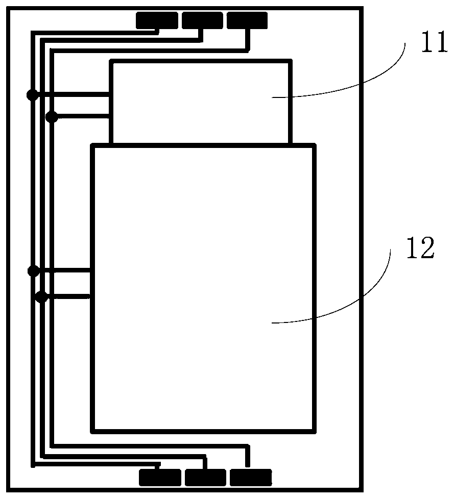
[0005] The invention provides a liquid crystal panel and a liquid crystal panel optical alignment method, which are used to solve the technical problem in the prior art that the cured lines cannot be discharged due to the increase of the cured lines

Method used


Image

  • Liquid crystal panel and liquid crystal panel photo-alignment method
  • Liquid crystal panel and liquid crystal panel photo-alignment method
  • Liquid crystal panel and liquid crystal panel photo-alignment method

Examples


Embodiment Construction

[0030] The present invention will be further described below in conjunction with accompanying drawing.

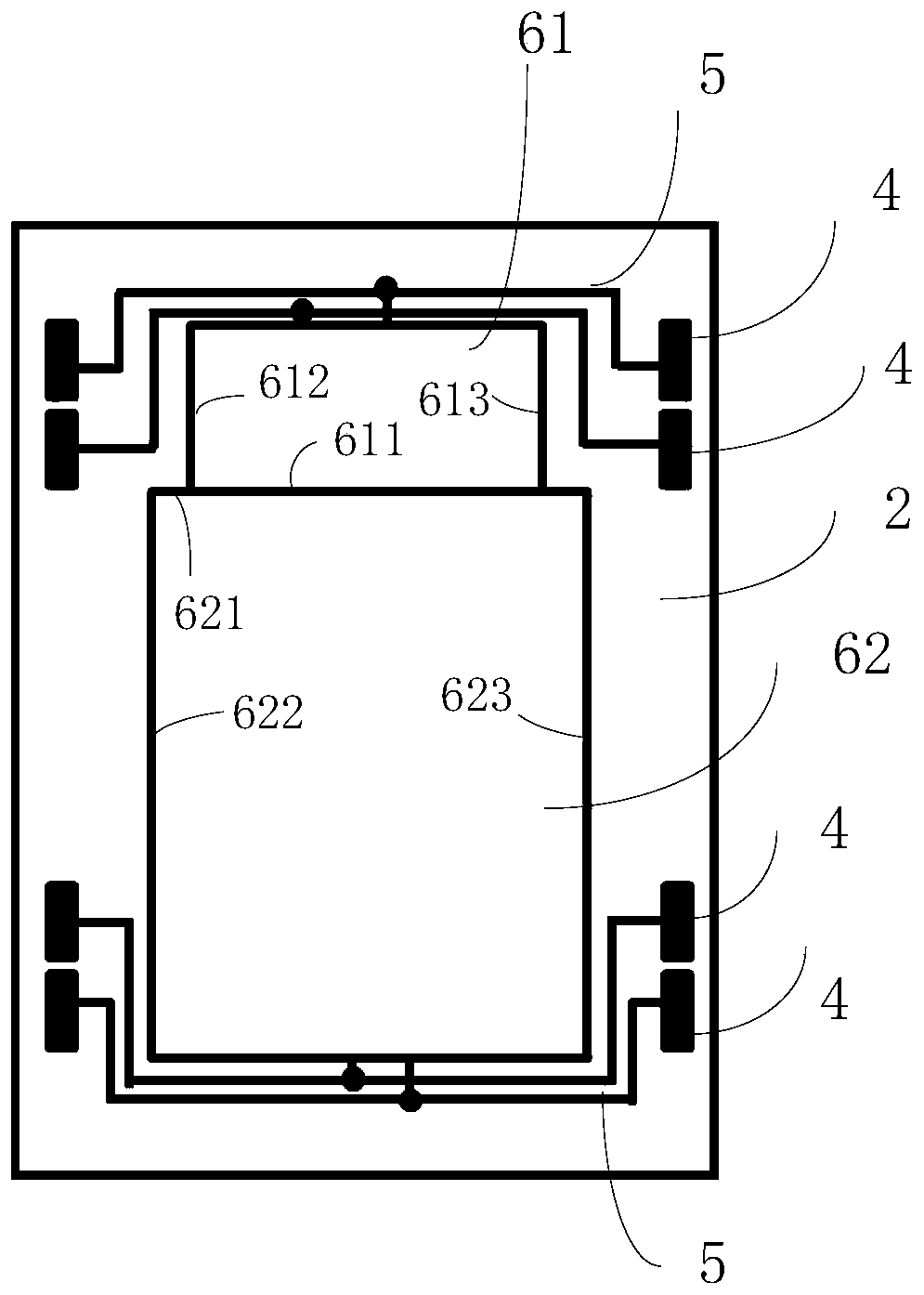
[0031] Please refer to image 3 , an embodiment of the present invention provides a liquid crystal panel, including: a color filter substrate 1, an array substrate 2, a curing connection terminal 4, a curing wiring 5 and a chipset, wherein the curing connection terminal 4, the curing wiring 5 and the chipset are all Arranged on the array substrate 2; the cured wiring 5 connects the cured connection terminal 4 with the chipset; the cured connection terminal 4 is used to connect the array substrate 2 and the color filter substrate 1; the chipset includes at least a first chip 61 and a second chip 62 , Optionally, the area of ​​the first chip 61 is smaller than that of the second chip 62; for the first chip 61 and the second chip 62, corresponding curing connection terminals 4 and curing traces 5 are respectively provided; during curing and voltage application, Curing Signal ...


PUM


Abstract

The invention provides a liquid crystal panel and a light alignment method of the liquid crystal panel. The liquid crystal panel includes a color film substrate and an array substrate; curing connection terminals, curing wires, and a chip group are arranged in a non-display zone of the array substrate; the curing connection terminals communicate with the chip group through the curing wires; the chip group at least includes a first chip and a second chip; the first chip and the second chip are provided with corresponding curing connection terminals and curing wires respectively. In a curing voltage applying process, a curing signal enters the corresponding first chip or second chip via the curing connection terminals and the curing wires from the color film substrate. The curing connection terminals and the curing wires of different chips are arranged separately, a space of each curing wire can be increased, signal delay difference between the chips at different positions is small, the problem that the space of the conventional curing wires is limited can be overcome, and electrostatic discharge (ESD) due to metal overline can be avoided.

Description

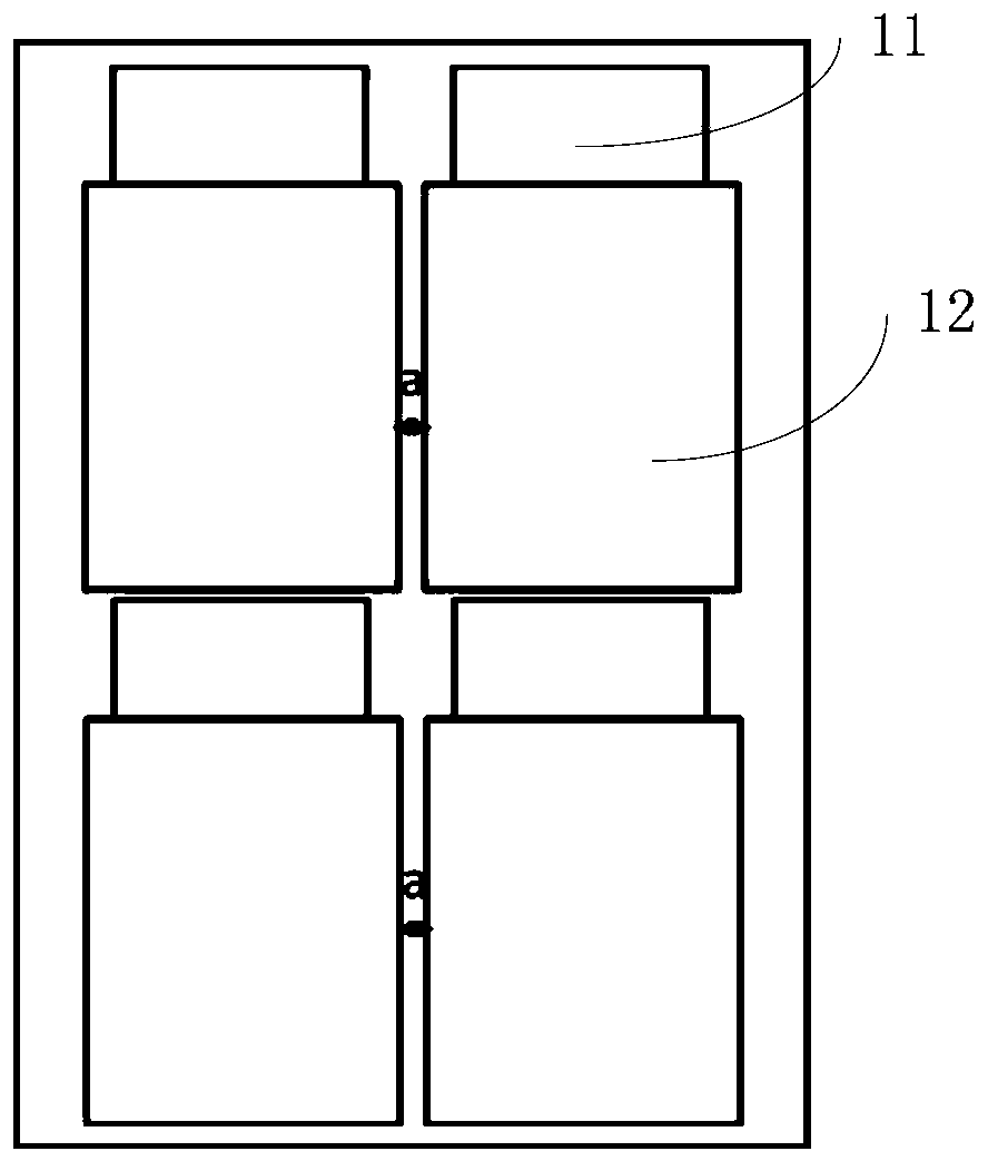
technical field [0001] The invention relates to liquid crystal display technology, in particular to a liquid crystal panel and a method for optical alignment of the liquid crystal panel. Background technique [0002] As large-size LCD TVs become more and more popular among consumers, the market for large-size LCD TVs has a good development trend. But at the same time, it is also accompanied by the problem that the utilization rate of large panels will be low during the production of large-size panels. The high production cost also makes the unit price of large-size LCD TVs high, limiting its market development. [0003] At present, the panel cutting technology is used to improve this defect, that is, large-size panels and small-size panels are combined into one large panel for production, which greatly reduces the production cost of large-size LCD TVs. However, as the size and number of chips increase, it is necessary to compress the space for curing wiring in the large gl...

Claims


Application Information

Patent Timeline
Patent Type & Authority Patents(China)
IPC IPC(8): G02F1/1362G02F1/1345G02F1/1343G02F1/1337
CPCG02F1/133788G02F1/134309G02F1/13454G02F1/136286G02F1/136295
Inventor 赵丽徐向阳
Owner TCL CHINA STAR OPTOELECTRONICS TECH CO LTD
Learn More