Building metal support pipe derusting device

A technology for metal support pipes and construction, which is applied in the field of rust removal devices for metal support pipes for construction, can solve the problems of low rust removal efficiency, inconvenient metal pipe rust removal, etc., and achieves convenient rotation control and convenient rotary rust removal treatment. Effect

Inactive Publication Date: 2017-03-29
SHANGHAI ZHAOYI ELECTRONICS TECH CO LTD
View PDF0 Cites 2 Cited by
  • Summary
  • Abstract
  • Description
  • Claims
  • Application Information

AI Technical Summary

Problems solved by technology

The existing rust remover is inconvenient to remove rust on metal pipes, especially metal support pipes for construction, and the rust removal efficiency is low

Method used


Image

  • Building metal support pipe derusting device

Examples


Embodiment Construction

[0012] In order to make the technical means, creative features, goals and effects achieved by the present invention easy to understand, the present invention will be further described below in conjunction with specific embodiments.

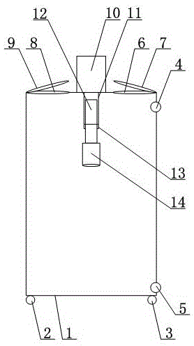
[0013] Such as figure 1 As shown, a metal support pipe derusting device for construction includes a derusting pool 1, and the bottom of the derusting pool 1 is provided with a first moving wheel 2 and a second moving wheel 3, and the first moving wheel 2 and the second moving wheel 3 have the same shape and size, the first moving wheel 2 and the second moving wheel 3 are universal wheels; the end of the derusting tank 1 is provided with a first liquid inlet 6, and the position of the first liquid inlet 6 is provided with a first The end cover 7, the end of the derusting tank 1 is provided with a second liquid inlet 8, and the second liquid inlet 8 is provided with a second end cover 9; the end of the derusting tank 1 is provided with a driving mot...


PUM

PropertyMeasurementUnit
particle sizeaaaaaaaaaa

Abstract

The invention discloses a building metal support pipe derusting device. The building metal support pipe derusting device comprises a derusting pool; a liquid inlet is formed in the end part of the derusting pool; a driving motor is arranged at the end part of the derusting pool, and is connected with a driving pipe; the driving pipe is arranged in the derusting pool; a driving shaft is sleeved with the driving pipe; a rotating pipe is arranged at the lower end of the driving pipe, and is connected with the lower end of the driving end through a buckle; the rotating pipe and the driving shaft are connected through a thread; and a sleeve is arranged at the lower end of the driving shaft, and is arranged in the derusting pool. A derusting agent can be poured into the derusting pool through the liquid inlet; a metal support pipe to be treated is mounted at the position of the sleeve; and the driving motor can realize rotation of the driving pipe and the driving shaft, so that the rotation control over the metal support pipe is conveniently achieved, and the rotary derusting treatment of the metal support pipe in the derusting liquid is convenient to perform.

Description

technical field [0001] The invention relates to a derusting device, in particular to a derusting device for metal support pipes used in construction. Background technique [0002] The derusting machine mainly uses the high-speed operation of mechanical equipment to throw steel shots of a certain particle size by the centrifugal force of the throwing head, and the thrown steel shots collide with the components violently to achieve the purpose of removing the rust on the steel surface. The types of steel shot it uses are: cast iron shot and steel wire cut shot. The cast iron shot is formed by spraying molten iron and cooling rapidly. It is relatively cheap but less durable. During the shot blasting process, the iron shot is crushed and discharged as dust after repeated impacts. Steel wire cut shot is made by cutting the steel wire of waste steel wire rope into 2mm small sections. Its surface has sharp corners, the rust removal effect is relatively high, and it is not easy to...

Claims


Application Information

Patent Timeline
Patent Type & Authority Applications(China)
IPC IPC(8): C23G3/04
Inventor 不公告发明人
Owner SHANGHAI ZHAOYI ELECTRONICS TECH CO LTD
Why Eureka
Try Eureka