An automatic hydraulic angle cutting machine for photo frame production and its realization method

An implementation method and technology of cutting angle machine, which are applied in special forming/shaping machines, forming/shaping machines, manufacturing tools, etc., can solve the problems of poor use effect, not easy to cut corners, uneven cutting surfaces, etc., and achieve structural Simple, easy to process, neat and beautiful effect

Active Publication Date: 2019-03-22
DONGYANG MINGSHUO MACHINERY EQUIP MFG CO LTD
View PDF8 Cites 0 Cited by
  • Summary
  • Abstract
  • Description
  • Claims
  • Application Information

AI Technical Summary

Problems solved by technology

In the prior art, when cutting the corners of the photo frame strips, most of them use manual corner cutting, or use a simple cutting knife to cut the corners. When cutting thicker and thicker photo frame strips, it is not easy to cut the corners, because the tangential The force is relatively large, and the cutting surface is not smooth, and the use effect is not good

Method used


Image

  • An automatic hydraulic angle cutting machine for photo frame production and its realization method
  • An automatic hydraulic angle cutting machine for photo frame production and its realization method
  • An automatic hydraulic angle cutting machine for photo frame production and its realization method

Examples


Embodiment 1

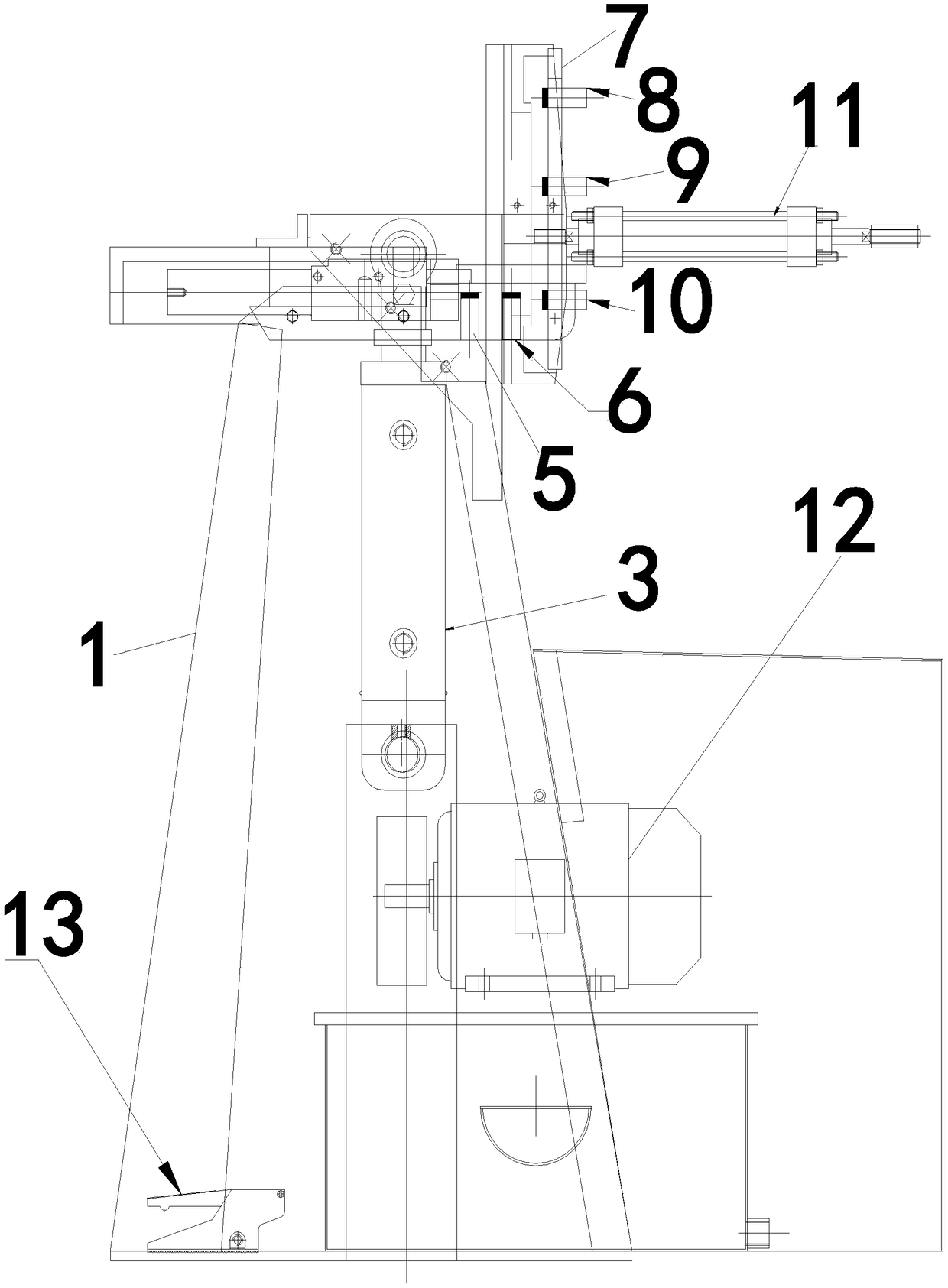
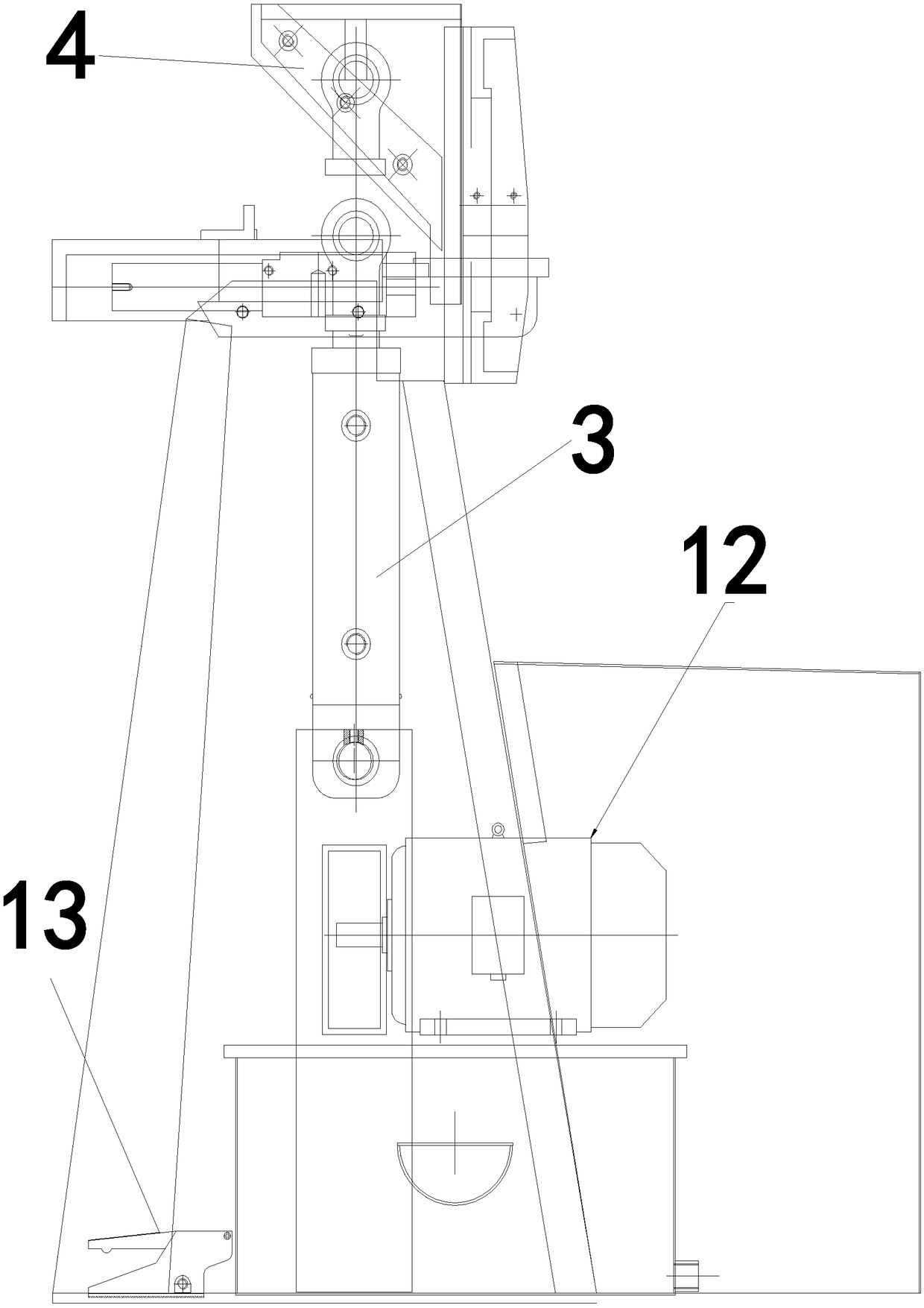
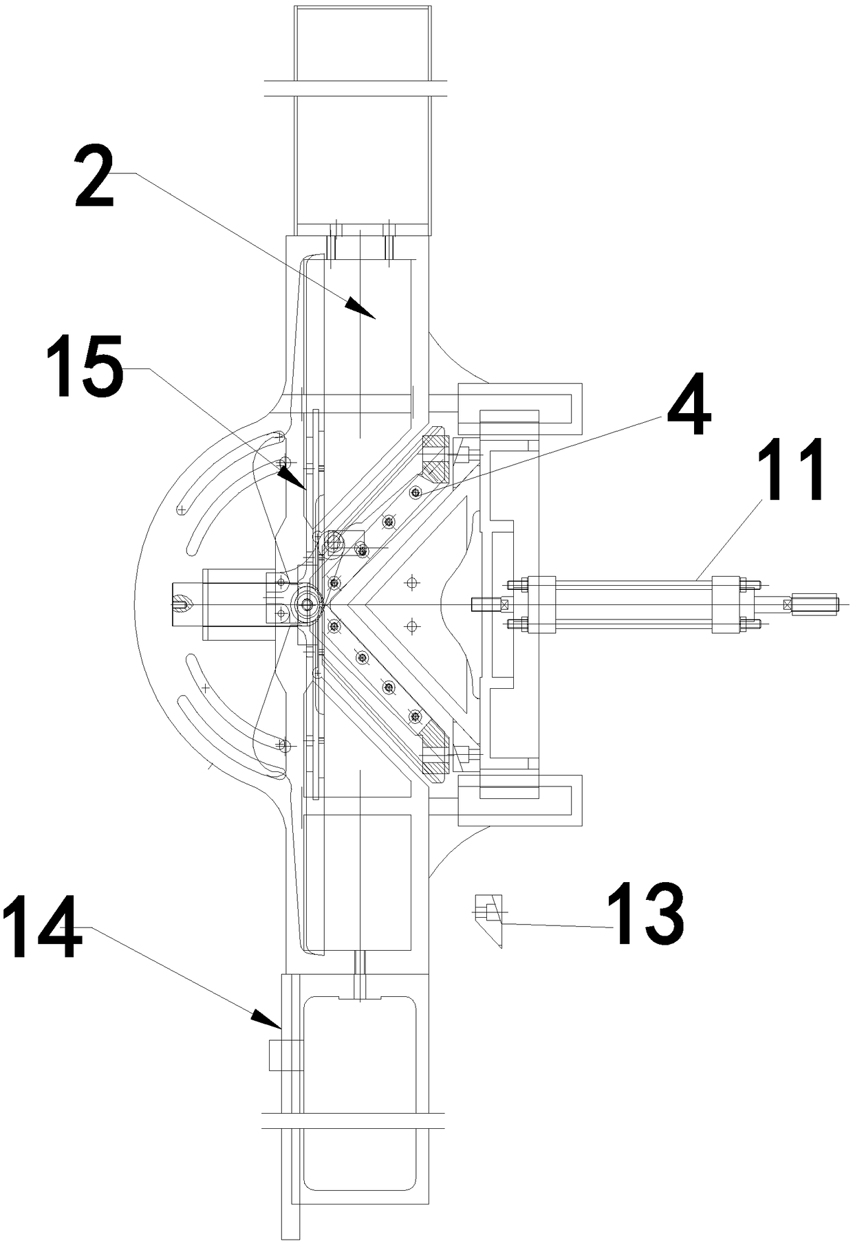
[0033] Such as Figure 1~3 As shown, an automatic hydraulic angle cutting machine for photo frame production, including a frame, a working platform is arranged on the frame, a longitudinal hydraulic cylinder is arranged under the working platform, and the longitudinal hydraulic cylinder is connected with a bevel cutter, and the horizontal position of the working platform is There is a left sensor switch and a right sensor switch, and a mounting plate is set on the side of the rack. The top limit sensor switch, the middle touch sensor switch and the bottom limit sensor switch are arranged on the mounting plate sequentially from top to bottom, and the middle touch sensor switch is below There is a horizontal hydraulic cylinder, which is connected to the oblique cutter, and the motor hydraulic pump is respectively connected to the longitudinal hydraulic cylinder and the horizontal hydraulic cylinder. Hydraulic pump, left sensor switch, right sensor switch, top limit sensor switch...


PUM


Abstract

The invention discloses an automatic hydraulic angle cutter for producing a picture frame. The automatic hydraulic angle cutter comprises a framework, a longitudinal hydraulic cylinder, a beveling knife, a left inductive switch and a right inductive switch, wherein the side edge of the framework is provided with a mounting plate; the mounting plate is provided with a top limit inductive switch, a middle touch inductive switch and a bottom limit inductive switch in sequence from top to bottom; a transverse hydraulic cylinder is arranged below the middle touch inductive switch; the transverse hydraulic cylinder is connected with the beveling knife; a motor hydraulic pump is connected with the longitudinal hydraulic cylinder and the transverse hydraulic cylinder respectively; a controller is arranged in an electric control cabinet; the controller is connected with the longitudinal hydraulic cylinder, the transverse hydraulic cylinder, the motor hydraulic pump, the left inductive switch, the right inductive switch, the top limit conductive switch, the middle touch inductive switch and the bottom limit inductive switch respectively. The invention also discloses a realization method of the automatic hydraulic angle cutter for producing the picture frame. The automatic hydraulic angle cutter for producing the picture frame has the characteristics of being simple in structure, low in manufacturing cost, tidy in section, high in production efficiency, high in degree of automation, and the like.

Description

technical field [0001] The invention relates to photo frame machinery technology, in particular to an automatic hydraulic angle cutting machine for photo frame production and its realization method. Background technique [0002] At present, the mounting of photos and pictures is mostly mounted with a photo frame. The photo frame is generally composed of four frame edges. During the processing, the wire is first cut into four pieces, and then nailed into one by a nail frame machine. In the prior art, when cutting the corners of the photo frame strips, most of them use manual corner cutting, or use a simple cutting knife to cut the corners. When cutting thicker and thicker photo frame strips, it is not easy to cut the corners, because the tangential The force is relatively large, and the cut surface is uneven, and the use effect is not good. Contents of the invention [0003] The object of the present invention is to overcome the shortcomings of the prior art above, and pr...

Claims


Application Information

Patent Timeline
Patent Type & Authority Patents(China)
IPC IPC(8): B27C5/02B27M3/24
CPCB27C5/02B27M3/24
Inventor 陈佩书何顺义
Owner DONGYANG MINGSHUO MACHINERY EQUIP MFG CO LTD
Why Eureka
Try Eureka