A jig for welding elbows of automobile mufflers

An automobile muffler and pipe bending technology, which is applied in welding equipment, auxiliary welding equipment, welding/cutting auxiliary equipment, etc., can solve the problems of inaccurate welding positioning, welding deformation and looseness at the joint between the bending pipe and the special-shaped plate, and achieves the guarantee Welding quality, effects of avoiding shifting or loosening

Active Publication Date: 2018-05-18
景和智能制造(广东)有限公司
View PDF4 Cites 0 Cited by
  • Summary
  • Abstract
  • Description
  • Claims
  • Application Information

AI Technical Summary

Problems solved by technology

Although these bent pipes and special-shaped plates have great advantages in terms of structure and force, they also have inconveniences. When the joints of bent pipes and special-shaped plates need to be welded, due to their irregular shapes, general fixtures are difficult to weld. Fix the bent pipe and the shaped plate, which brings a lot of inconvenience to the welding between the bent pipe and the shaped plate
The welding positioning of the elbow and the special-shaped plate is inaccurate. If it is light, it may cause uneven welding force at the joint between the elbow and the special-shaped plate, and the welding quality is low. If it is serious, it may cause welding deformation at the joint between the elbow and the special-shaped plate.
[0003] Especially for muffler pipes that need to be welded by elbows with different bending angles at both ends, it is difficult to clamp and fix the elbows with existing fixtures, and the elbows will shift or loosen during the welding process, while Makes welding difficult and often results in weld distortion or poor quality welds

Method used


Image

  • A jig for welding elbows of automobile mufflers
  • A jig for welding elbows of automobile mufflers
  • A jig for welding elbows of automobile mufflers

Examples


Embodiment Construction

[0026] The present invention will be further described below in conjunction with the drawings and embodiments.

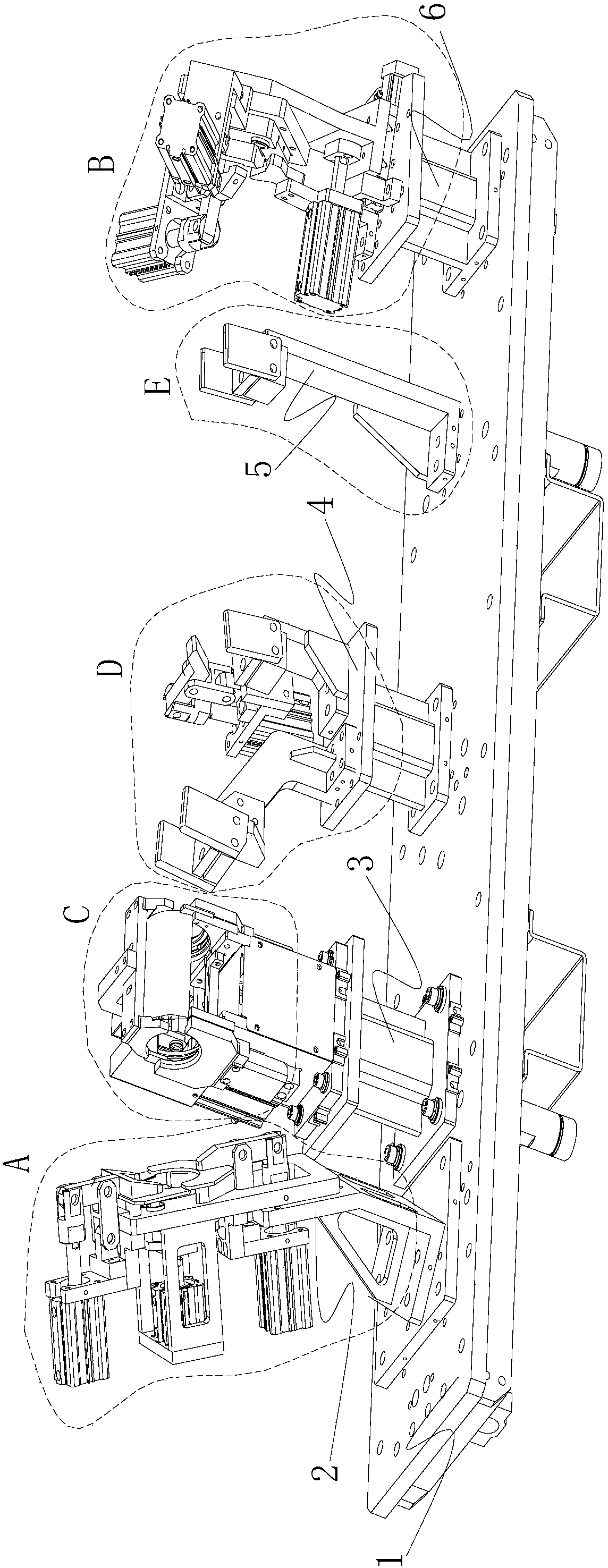
[0027] As shown in the figure, the fixture for welding elbow pipe of automobile muffler is provided with a left clamping seat 2, a first support frame 3, a second support frame 4, and a third support on the frame 1 of the fixture in turn from left to right The frame 5 and the right clamping base 6, the first supporting frame 3, the second supporting frame 4 and the third supporting frame 5 are arranged in sequence, and the first supporting frame 3 is closest to the left clamping base 2.

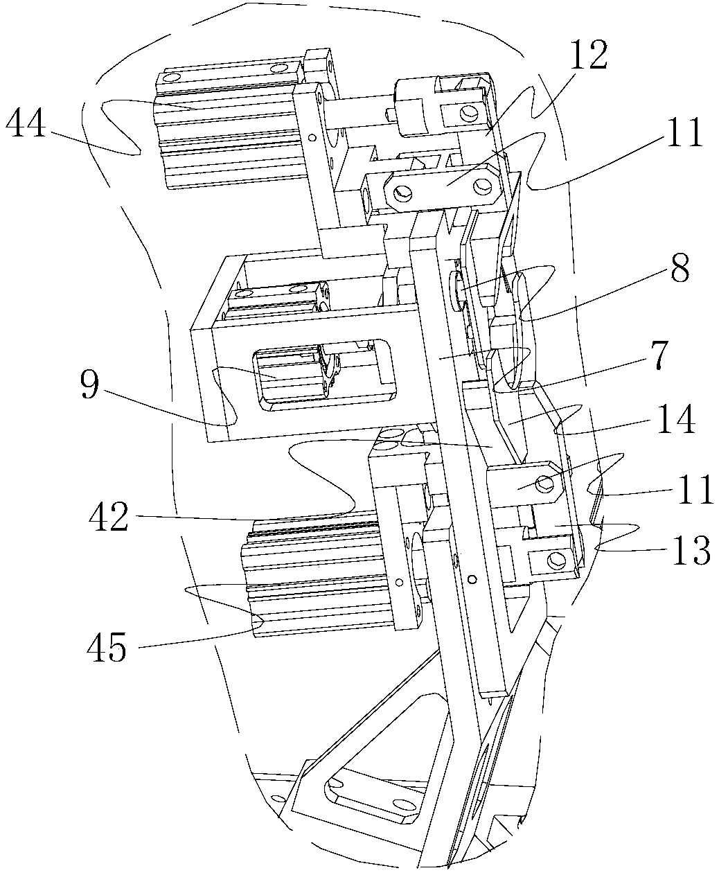
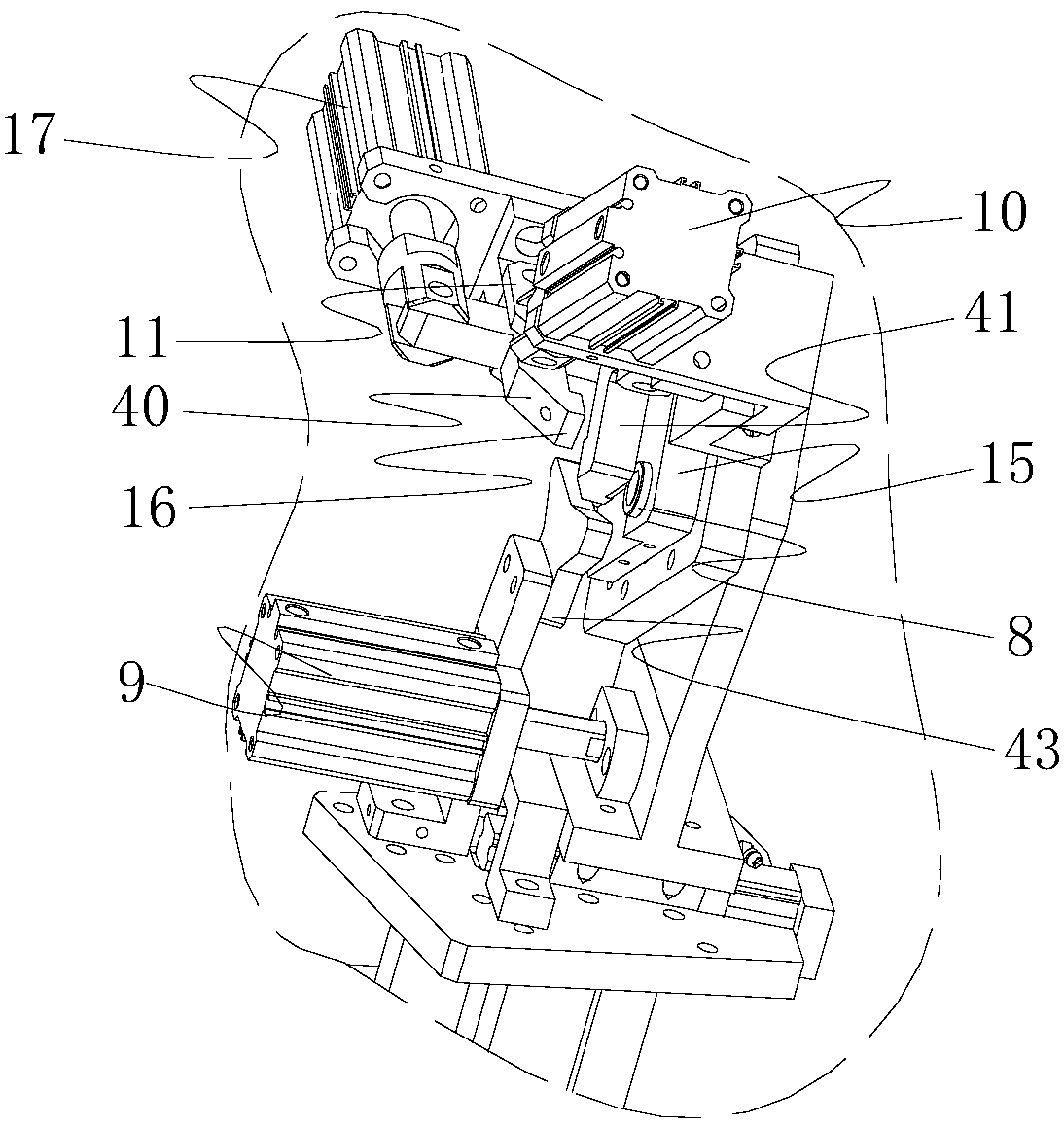
[0028] In this embodiment, the left clamping seat 2 includes a left support table 7 having a plate-like structure. The left support table 7 is provided with three support columns 8 for workpiece positioning and a support column cylinder 9 as a support column power mechanism. The piston rod of the support column cylinder 9 is connected to each support column 8 through a connecting plate,...


PUM


Abstract

The invention discloses a clamp used for welding a car silencer elbow. The clamp comprises a rack. The rack is provided with a left clamping base and a right clamping base. The left clamping base comprises a left supporting table. The left supporting table is provided with a left bearing block. A first left clamping arm and a second left clamping arm are arranged above the left bearing block. The first left clamping arm and the second left clamping arm are provided with pressing plates correspondingly. The right clamping base comprises a right supporting table which is provided with a right bearing block. A first right clamping arm and a second right clamping arm are arranged above the right bearing block. The first right clamping arm and the second right clamping arm are provided with pressing blocks correspondingly. The rack is further provided with a first supporting frame, a second supporting frame and a third supporting frame which are located between the left clamping base and the right clamping base. The clamp enables the elbow to be fixed and located accurately, the phenomenon that the elbow shifts or loosens is avoided, and the welding quality of the elbow is ensured.

Description

Technical field [0001] The invention relates to the processing of automobile parts and components, in particular to a clamp used for an automobile muffler elbow welding machine. Background technique [0002] In today's society, cars have become an indispensable means of transportation for people. Cars have changed the way people travel and have profoundly affected all aspects of society. Of course, as a product of science and technology, with the development of society and technological innovation, the structure of automobiles is becoming more and more complex, and the performance of automobiles is getting better and better. There are many bends and special-shaped plates in the structure of the car. The existence of these bends and special-shaped plates not only improves the structural connection inside the car, makes the car structure more compact, but also makes the structural performance of the car great Improvement. These bends and special-shaped plates usually have a varie...

Claims


Application Information

Patent Timeline
Patent Type & Authority Patents(China)
IPC IPC(8): B23K37/053
CPCB23K37/0533B23K2101/006
Inventor 伍朝砖
Owner 景和智能制造(广东)有限公司
Why Eureka
Try Eureka