Camera assembly

A camera component and camera technology, applied to electrical components, parts of connecting devices, base/housing, etc., can solve problems such as abnormal function of body parts, display water ripples, display flickering, etc., to facilitate miniaturization design and improve sealing Sexuality, good waterproof effect

Pending Publication Date: 2017-03-22
SHENZHEN LONGHORN AUTOMOTIVE ELECTRONICS EQUIPCO
View PDF8 Cites 2 Cited by
  • Summary
  • Abstract
  • Description
  • Claims
  • Application Information

AI Technical Summary

Problems solved by technology

[0002] As cars become more and more popular, car accessories are also attracting attention. At the same time, everyone has higher and higher requirements for car safety performance; the driving assistance vision system can greatly reduce collisions and traffic accidents, although the current driving assistance vision of the car The system is usually equipped with a vehicle-mounted camera. Since the vehicle-mounted camera is installed on the surface of the car, it has high requirements for waterproof performance; at the same time, since the camera component contains a PCBA board and a camera, the PCBA board is equipped with an integrated circuit, and the signal interaction with the camera exists. Interference problem, signal interference of other parts of the car body will cause abnormal phenomena such as display water ripples, display flickering, abnormal white spots, etc. Camera signal interference will also cause abnormal functions of other car body parts
The existing improvement method is to add a metal shielding cover before and after the camera PCBA board to achieve the shielding effect. This method has a complex structure and process, and the cost of parts is high. There are many parts and it is not conducive to the miniaturization design of the camera.

Method used


Image

  • Camera assembly
  • Camera assembly
  • Camera assembly

Examples


Embodiment Construction

[0020] The present application will be described in further detail below in conjunction with the accompanying drawings and specific embodiments. It should be understood that the following exemplary embodiments and descriptions are only used to explain the present invention, not as a limitation to the present invention, and, in the case of no conflict, the embodiments in the application and the features in the embodiments can be combined with each other .

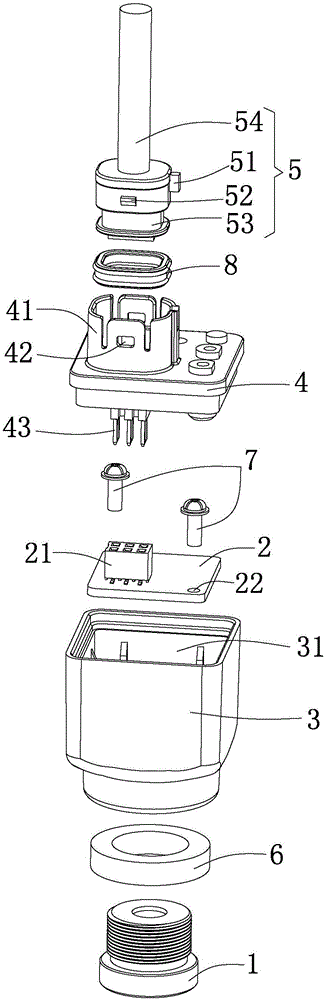
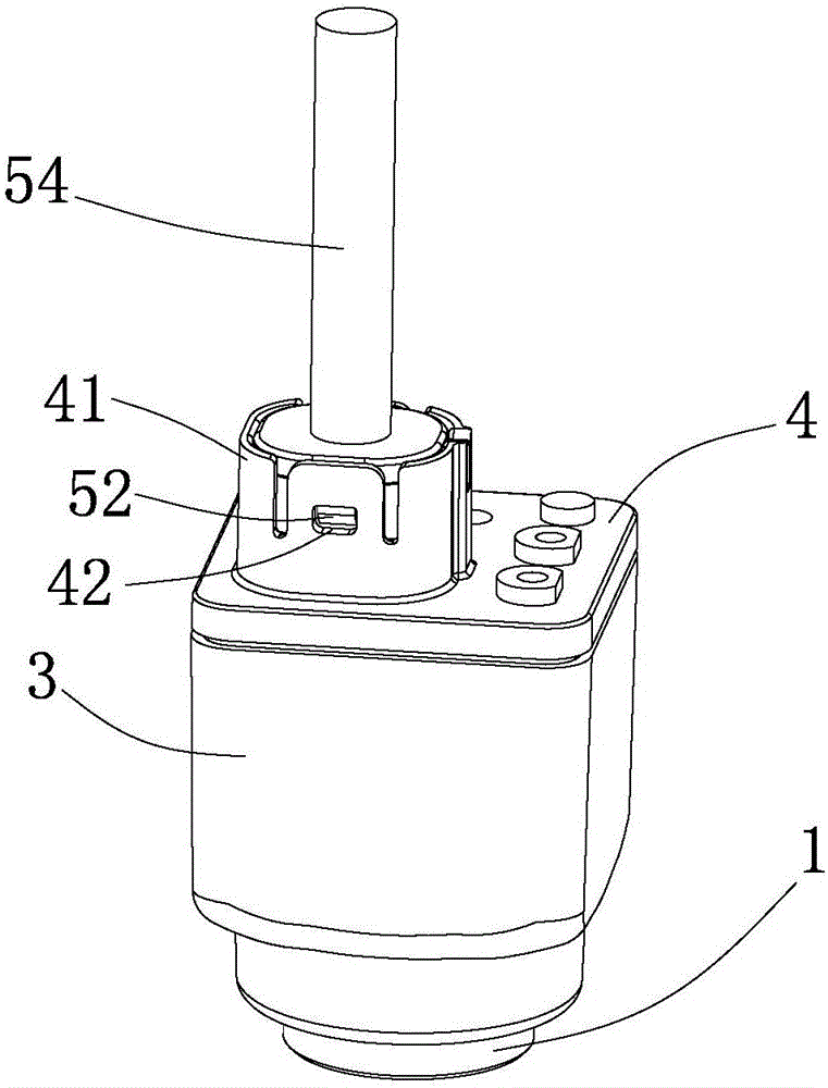
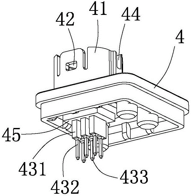
[0021] Such as figure 1 , figure 2 and Figure 5 As shown, the embodiment of the present invention provides a camera assembly, including a camera 1, a PCBA board 2, a housing 3 having a hollow cavity and openings at both ends, and a shell for closing the opening 31 at the first end of the housing 3 Cover 4 and harness 5.

[0022] The PCBA board 2 is accommodated in the hollow cavity of the housing 3, and the camera 1 is installed at the second end opening (not labeled) of the housing 3 and is electrically connected to t...


PUM


Abstract

The embodiment of the invention provides a camera assembly, comprising a camera, a PCBA (Printed Circuit Board Assembly) board and a harness. The camera assembly further comprises a shell having a hollow cavity and two ends opened and a shell cover for closing the first end opening of the shell; the PCBA board is accommodated in the hollow cavity of the shell, and the camera is installed at the second end opening of the shell and electrically connected with the PCBA board; the PCBA board is provided with a first electrical connector, a second electrical connector penetrating the shell cover is arranged on the shell cover, and the first end of the second electrical connector inside the shell cover and the second end outside the shell cover are electrically connected with the first electrical connector and the harness respectively; and electromagnetic shielding layers are formed on the inner walls of the shell and the shell cover. The electromagnetic shielding layers are formed on the inner walls of the shell and the shell cover, so that the structure of the camera assembly is simplified, miniature design of the camera assembly is facilitated, meanwhile, the sealing property of the camera assembly is improved, and better waterproof performance is further achieved.

Description

technical field [0001] The present invention relates to the technical field of camera components, in particular to a vehicle-mounted camera component. Background technique [0002] As cars become more and more popular, car accessories are also attracting attention. At the same time, everyone has higher and higher requirements for car safety performance; the driving assistance vision system can greatly reduce collisions and traffic accidents, although the current driving assistance vision of the car The system is usually equipped with a vehicle-mounted camera. Since the vehicle-mounted camera is installed on the surface of the car, it has high requirements for waterproof performance; at the same time, since the camera component contains a PCBA board and a camera, the PCBA board is equipped with an integrated circuit, and the signal interaction with the camera exists. Interference problem, signal interference of other parts of the car body will cause abnormal phenomena such as...

Claims


Application Information

Patent Timeline
IPC IPC(8): H01R13/52H01R13/6581H01R12/71
CPCH01R13/5202H01R12/71H01R13/5227H01R13/6581
Inventor 罗小平麦福利
Owner SHENZHEN LONGHORN AUTOMOTIVE ELECTRONICS EQUIPCO
Why Eureka
Try Eureka