UAV landing control method and device
A control method and technology of unmanned aerial vehicles, which are applied in non-electric variable control, altitude or depth control, control/regulation systems, etc. The effect of operating the threshold
- Summary
- Abstract
- Description
- Claims
- Application Information
AI Technical Summary
Problems solved by technology
Method used
Image

Examples
Embodiment 1
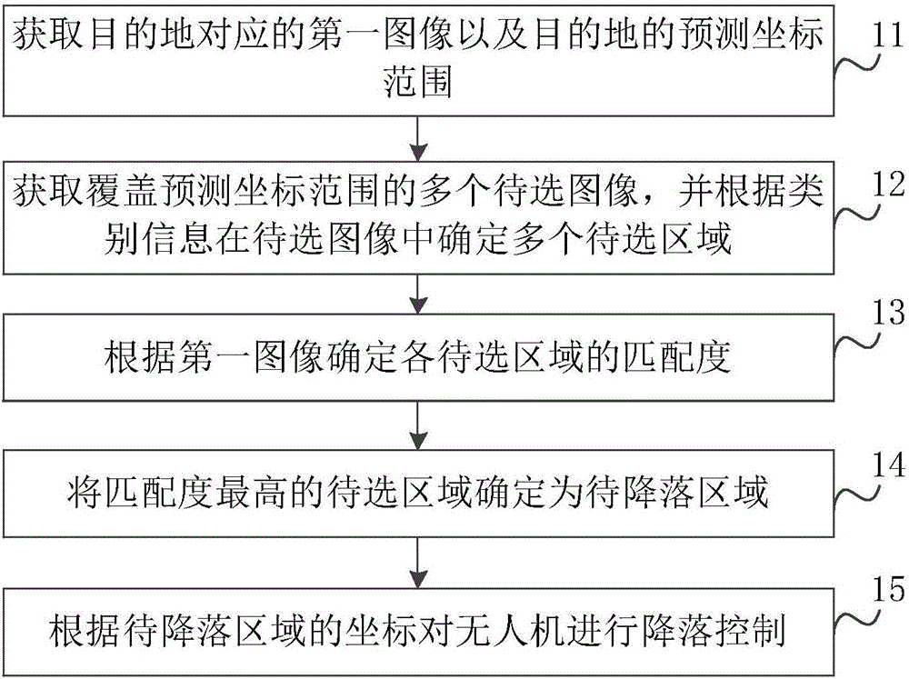
[0039] figure 1 A flowchart showing a method for controlling a landing of a drone according to an embodiment of the present disclosure. The method can be applied to a ground station or an unmanned aerial vehicle, which is not limited here. Among them, the ground station can communicate with the drone wirelessly to control the landing of the drone. Such as figure 1 As shown, the method may include step 11 to step 15.
[0040] In step 11, the first image corresponding to the destination and the predicted coordinate range of the destination are acquired.
[0041] Wherein, the first image corresponding to the destination may be an image obtained by photographing the destination in advance, or may be an image having graphic features of the destination, which is not limited herein. For example, if Figure 6aAs shown, the destination is an object W, and the first image corresponding to the destination may be an image obtained by photographing the object W in advance, or may be a...
Embodiment 2
[0085] Figure 7 A structural diagram showing an unmanned aerial vehicle landing control device according to an embodiment of the present disclosure, such as Figure 7 As shown, the UAV landing control device includes: a destination information acquisition module 100, configured to acquire a first image corresponding to the destination and a predicted coordinate range of the destination. The candidate area acquisition module 200 is configured to acquire multiple candidate images covering the predicted coordinate range, and determine multiple candidate areas in the candidate images according to category information. A matching degree determining module 300, configured to determine the matching degree of each of the regions to be selected according to the first image. The to-be-landing area determining module 400 is configured to determine the candidate area with the highest matching degree as the to-be-landed area. The landing control module 500 is configured to control the l...
Embodiment 3
[0097] Figure 9 It is a block diagram of a device 800 for drone landing control shown according to an exemplary embodiment. For example, the apparatus 800 may be a mobile phone, a computer, a digital broadcast terminal, a messaging device, a game console, a tablet device, a medical device, a fitness device, a personal digital assistant, and the like.
[0098] refer to Figure 9 , the apparatus 800 may include one or more of the following components: a processing component 802, a memory 804, a power supply component 806, a multimedia component 808, an audio component 810, an input / output (I / O) interface 812, a sensor component 814, and a communication component 816.
[0099] The processing component 802 generally controls the overall operations of the device 800, such as those associated with display, telephone calls, data communications, camera operations, and recording operations. The processing component 802 may include one or more processors 820 to execute instructions ...
PUM
 Abstract
Description
Claims
Application Information
 - Generate Ideas
- Intellectual Property
- Life Sciences
- Materials
- Tech Scout
- Unparalleled Data Quality
- Higher Quality Content
- 60% Fewer Hallucinations
Browse by: Latest US Patents, China's latest patents, Technical Efficacy Thesaurus, Application Domain, Technology Topic, Popular Technical Reports.
© 2025 PatSnap. All rights reserved.Legal|Privacy policy|Modern Slavery Act Transparency Statement|Sitemap|About US| Contact US: help@patsnap.com