
Fuselage conductive structure of unmanned aerial vehicle and manufacturing method of fuselage frames

A fuselage frame and conductive structure technology, applied in the fuselage frame, unmanned aircraft, fuselage and other directions, can solve the problems of self-heavy, complex structure, many electrical circuits, etc., to facilitate replacement, reduce power supply components, Overall weight reduction effect

Active Publication Date: 2017-03-22
XIAMEN HANHANG PRECISION TECH CO LTD
View PDF6 Cites 2 Cited by
  • Summary
  • Abstract
  • Description
  • Claims
  • Application Information

AI Technical Summary

Problems solved by technology

[0005] The object of the present invention is to provide a fuselage conductive structure and a manufacturing method of the fuselage frame of the UAV. To solve the problem of many lines and heavy weight, the structural components of the fuselage and its internal electrical lines are integrated to ensure the structural strength of the electrical line carrier while achieving stable output of large currents and effective reduction of structural weight, improving battery life.

Method used


Image

  • Fuselage conductive structure of unmanned aerial vehicle and manufacturing method of fuselage frames
  • Fuselage conductive structure of unmanned aerial vehicle and manufacturing method of fuselage frames
  • Fuselage conductive structure of unmanned aerial vehicle and manufacturing method of fuselage frames

Examples


Embodiment Construction

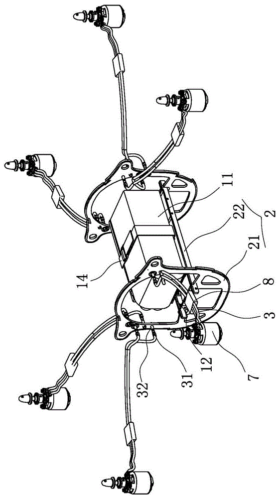
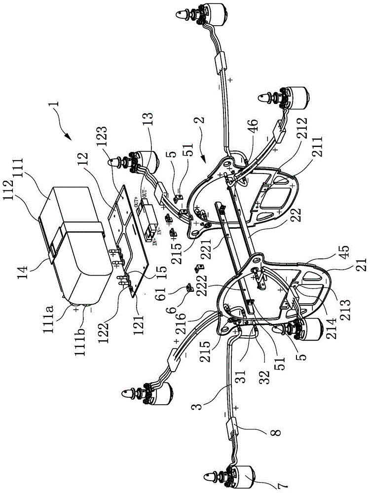
[0046] Such as Figure 1-9 As shown, the conductive structure of the fuselage of the drone disclosed in Embodiment 1 of the present invention includes a battery pack 1, a fuselage assembly 2 and a power supply wire 3 for the blade motor;

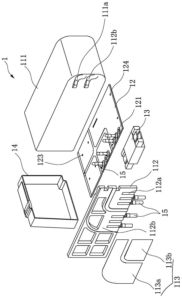
[0047] The battery pack 1 includes a lithium battery pack body 11 and a power supply circuit board 12. The positive and negative output terminals of the lithium battery pack body 11 are welded with single-row in-line banana sockets 14, the power supply circuit board 12 is a double-sided board, and the power supply circuit board 12 Banana plugs 15 are arranged on one side corresponding to the banana sockets, inserted vertically through the banana sockets 14 and welded on two pairs of banana plugs 15, so that the battery pack 11 body is installed on the power supply circuit board 12;

[0048] The fuselage assembly 2 is composed of two fuselage frames 21 and two fuselage beams 22. The fuselage frames 21 and the fuselage beams 22 are made of a t...


PUM

PropertyMeasurementUnit
Thicknessaaaaaaaaaa
Thicknessaaaaaaaaaa

Abstract

The invention discloses a fuselage conductive structure of an unmanned aerial vehicle and a manufacturing method of fuselage frames, the fuselage conductive structure comprises a battery pack, a fuselage assembly and blade motor power supply wires; the battery pack includes a lithium battery pack body and a power supply circuit board, the fuselage assembly includes two fuselage frames and two fuselage cross beams, the fuselage frames and the fuselage cross beams are respectively prepared from a thickening-type double-sided copper clad plate which is double-sided printed with conductive layers, the fuselage frames are respectively arranged at trisection cross sections in a fuselage cabin, PI shaped supporting structures are formed on the fuselage frames, two ends of the fuselage cross beams are respectively fixed on the PI shaped supporting structures of the two fuselage frames, the two fuselage frames are also provided with banana jacks, and a plurality of groups of blade motor power supply wires are in plug connection with the power supply banana jacks of the fuselage frames. The fuselage conductive structure has the advantages of simple structure, light weight and compact structure, and solves the problems of a complex fuselage mechanical structure and many electrical circuits of a traditional multi-rotor unmanned aerial vehicle, the weight of the fuselage structure is reduced, meanwhile a stable large current output is realized, and time of endurance is improved.

Description

technical field [0001] The invention relates to a fuselage conductive structure of an unmanned aerial vehicle and a manufacturing method thereof. Background technique [0002] Unmanned aircraft, referred to as "drone" for short, and "UAV" for English abbreviation, is an unmanned aircraft controlled by radio remote control equipment and its own program control device. From a technical point of view, it can be divided into: unmanned fixed-wing aircraft, unmanned vertical take-off and landing aircraft, unmanned airship, unmanned helicopter, unmanned multi-rotor aircraft, unmanned parawing aircraft, etc. [0003] The existing common electric multi-rotor UAVs are all powered by lithium batteries. When the power supply system supplies power to the power motor on the outermost edge of the machine arm, it needs to connect long and thick power wires. It is difficult to avoid the problem of self-heaviness in the traditional fuselage structure. In the case of the same task load weight...

Claims


Application Information

Patent Timeline
IPC IPC(8): B64C1/00B64C1/06B64D47/00
CPCB64C1/00B64C1/06B64D47/00B64U50/19Y02T50/40
Inventor 王麒麟苏志强
Owner XIAMEN HANHANG PRECISION TECH CO LTD
Learn More