Automatic centering electric rotating chuck

An electric rotation and automatic centering technology, applied in auxiliary devices, applications, laser welding equipment, etc., can solve problems such as unsuitable clamping of pipe fittings, large force on coil springs, and reduced machining accuracy.

Active Publication Date: 2017-03-22
SHANDONG LEIMING CNC LASER EQUIP CO LTD
View PDF9 Cites 16 Cited by
  • Summary
  • Abstract
  • Description
  • Claims
  • Application Information

AI Technical Summary

Problems solved by technology

The two collets used in the existing pipe cutting machine are respectively a rotary collet and a sliding collet. The rotary collet is usually a four-jaw blind hole rotary collet, and the sliding collet is a through-hole collet. The sliding collet is equipped with a cutting The laser head of the pipe adopts the four-jaw blind hole rotary chuck, which has the following disadvantages. First, it will inevitably lead to the growth of the pipe cutting machine body, and its length must be greater than the length of the pipe; second, the existing four-jaw blind hole rotary chuck cannot automatically align Among them, manual centering is required, and the centering is difficult, which leads to the installation time of the workpiece is much longer than the processing time of a pipe, and the processing efficiency is low; the third is that the existing rotary chuck is usually equipped with auxiliary fixtures to expand the variable diameter stroke. Because the collet’s variable diameter stroke cannot be in place at one time, it is usually necessary to adjust the auxiliary fixture, which further increases the difficulty of centering; Fourth, the existing rotary chuck with an internal circuit or air circuit generally cannot rotate in a full circle. It is impossible to solve the winding problem of the internal circuit or gas circuit caused by the full circle rotation; fifth, because the four claws of the existing rotary chuck are clamped synchronously, it is mainly suitable for clamping round, square and other pipe fittings. For rectangular, Irregular fittings are not suitable for clamping
[0005] In response to the above problems, many scientific researchers have devoted themselves to it and made some achievements. For example, the patent titled Rotary Chuck and Laser Pipe Cutting Machine (Application No.: 201510513625.2) discloses a rotary chuck. The head is a through-hole rotary chuck, and its clamping of the pipe mainly relies on the elastic force of the coil spring to drive the jaw block to rotate to clamp the pipe. Although it solves some problems of the blind-hole rotary chuck to a certain extent, but The shortcomings are also very obvious. Since the coil spring is used as the driving force for clamping, this will inevitably lead to uncontrollable clamping. Moreover, due to the gravity of the pipe itself, the force of the coil spring at the lower part is large, which can easily lead to misalignment or eccentricity. , the processing accuracy is difficult to guarantee; and the coil spring is easy to fatigue after long-term use, resulting in a decrease in clamping force, and the eccentricity problem will be more serious, and the processing accuracy is further reduced due to the centrifugal effect during the rotation of the pipe fittings. This patent is still not thorough. To solve the problem of automatic centering of pipe fittings, it is necessary to design a controllable self-centering through-hole rotary chuck

Method used


Image

  • Automatic centering electric rotating chuck
  • Automatic centering electric rotating chuck
  • Automatic centering electric rotating chuck

Examples


Embodiment Construction

[0030] Below in conjunction with accompanying drawing and embodiment, the present invention will be further described:

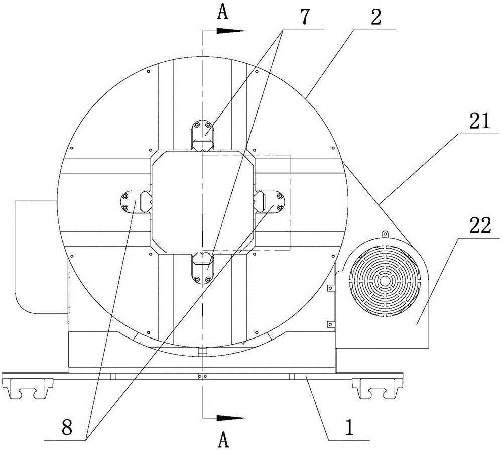
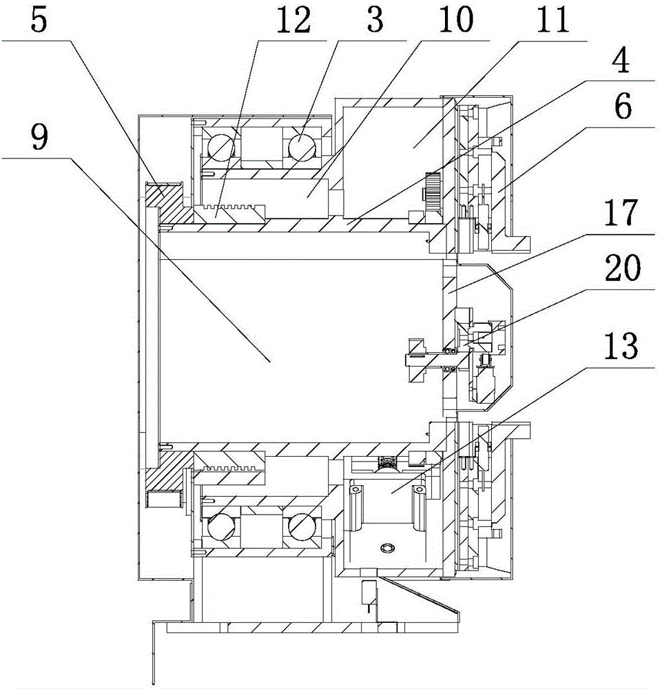
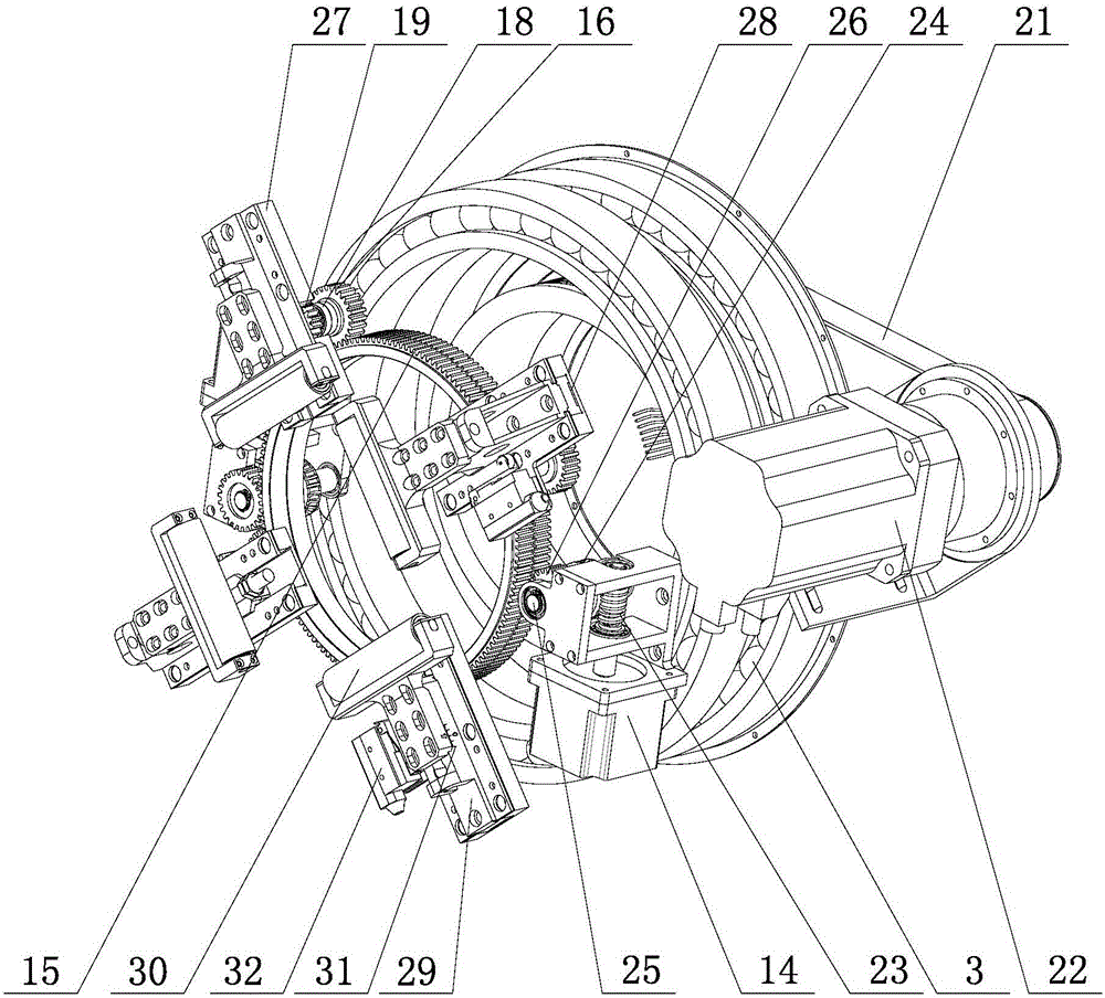
[0031] like Figure 1-3 As shown, an automatic centering electric rotating chuck includes a base 1, a bearing seat 2 is arranged on the base 1, a bearing 3 is arranged in the bearing seat 2, the inner ring of the bearing 3 is connected with the rolling core 4, and one end of the rolling core 4 is connected There is a rolling core drive device, and the other end of the rolling core end wall is provided with two sets of clamping jaw mechanisms 6 arranged in a cross shape. The two clamping jaw mechanisms 6 are the second group of clamping jaw mechanisms 8 , at least one clamping jaw mechanism 6 in each group of clamping jaw mechanisms is provided with a sensor 32 , the center of the rolling core 4 is provided with a through hole 9 , and the inner wall of the rolling core 4 is provided with a sensor 32 . There are a first cavity 10 and a second cavity 11, the f...


PUM


Abstract

Disclosed is an automatic centering electric rotating chuck. The automatic centering electric rotating chuck comprises a base; a bearing seat is arranged on the base; bearings are disposed in the bearing seat; inner rings of the bearings are connected with a roll core; one end of the roll core is connected with a roll core driving device, and the end wall of the other end of the roll core is provided with two sets of clamping jaw mechanisms which are arranged in a cross shape; the first set of clamping jaw mechanisms includes two clamping jaw mechanisms which are arranged in a longitudinal symmetry mode, and the second set of clamping jaw mechanisms includes two clamping jaw mechanisms which are arranged in a left-right symmetry mode; at least one clamping jaw mechanism of each set of clamping jaw mechanisms is provided with a sensor; a through hole is formed in the center of the roll core; a first cavity and a second cavity are formed in the wall of the roll core; an electric conductive sliding ring is disposed in the first cavity; two clamping jaw driving mechanisms for driving the first set of clamping jaw mechanisms and the second set of clamping jaw mechanisms correspondingly are disposed in the second cavity; and the electric conductive sliding ring is connected with the clamping jaw driving mechanisms through conducting wires. The automatic centering electric rotating chuck has the advantages of achieving through hole clamping, being provided with two sets of clamping jaws, achieving automatic and reliable centering and complete rotation, and the like.

Description

[0001] Technical field: [0002] The invention relates to the technical field of rotary chucks, in particular to an automatic centering electric rotary chuck. [0003] Background technique: [0004] The rotary chuck is one of the most important parts of the pipe cutting machine. When the pipe profile is processed, it is usually clamped by two chucks for cutting. The two chucks rotate synchronously during cutting, and one of the chucks can translate along the axial direction. The head cooperates to complete the three-axis linkage of X, Y, and Z to meet the cutting shape we need. The existing pipe cutting machines basically use the above working principle. The two chucks used in the existing pipe cutting machines are a rotary chuck and a sliding chuck. The rotary chuck is usually a four-jaw blind-hole rotary chuck, and the sliding chuck is a through-hole chuck. For the laser head of the pipe, the use of the four-jaw blind hole rotary chuck has the following disadvantages. First,...

Claims


Application Information

Patent Timeline
IPC IPC(8): B23K26/38B23K26/70B23K37/053B23K101/06
CPCB23K26/38B23K26/702B23K37/0533B23K2101/06
Inventor 李峰西杜祥安邰家欣
Owner SHANDONG LEIMING CNC LASER EQUIP CO LTD
Why Eureka
Try Eureka