
Micropore atomizer control circuit and power supply state indication method

A control circuit and microporous atomization technology, which is applied in the field of atomizers, can solve the problems of small mold size, omission of indicating circuit, insufficient use of IO pins of the chip, etc., and achieve the effect of ensuring stability and consistency

Active Publication Date: 2017-03-22
CHIPSEA TECH SHENZHEN CO LTD
View PDF9 Cites 12 Cited by
  • Summary
  • Abstract
  • Description
  • Claims
  • Application Information

AI Technical Summary

Problems solved by technology

In some products, there are limiting factors such as the small size of the mold, insufficient IO pins of the chip, and the reluctance to increase the cost of drilling holes on the surface of the mold or performing thinning and light-transmitting treatments. The status indication circuit is often omitted

Method used


Image

  • Micropore atomizer control circuit and power supply state indication method
  • Micropore atomizer control circuit and power supply state indication method
  • Micropore atomizer control circuit and power supply state indication method

Examples


Embodiment Construction

[0037] In order to make the object, technical solution and advantages of the present invention clearer, the present invention will be further described in detail below in conjunction with the accompanying drawings and embodiments. It should be understood that the specific embodiments described here are only used to explain the present invention, not to limit the present invention.

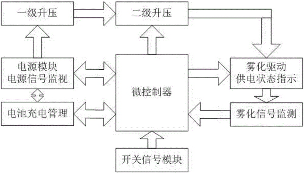
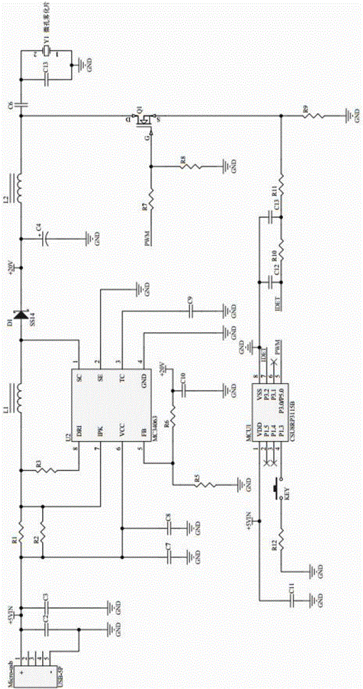
[0038] figure 1 As shown, the microporous atomizer control circuit realized by the present invention includes a microcontroller, a power supply and a power signal detection module, a first-stage boost module, a second-stage boost module, an atomization drive indicating module, and an atomization signal monitoring module. module, wherein the microcontroller is used as the control core, and the power supply and power signal detection module, the secondary boost module, the atomization drive indication module and the atomization signal monitoring module are all connected to the microcontroller.

[00...


PUM


Abstract

The invention discloses a micropore atomizer control circuit and a power supply state indication method. The control circuit comprises a microcontroller, a power source and power source signal detection module, a first-level boosting module, a second-level boosting module, an atomization driving indication module and an atomization signal monitoring module. The microcontroller serves as a control core, and the power source and power source signal detection module, the second-level boosting module, the atomization driving indication module and the atomization signal monitoring module are all connected to the microcontroller. By means of the micropore atomizer control circuit and the power supply state indication method, stability and consistency of driving voltage applied in the working process of a micropore atomizer can be guaranteed; the micropore atomizer under different power-supply power sources can have the same driving voltage so that the micropore atomizer in the resonance oscillation state can achieve the consistent atomization effect; and meanwhile, state indication is conducted through atomization pieces instead of LED, and safety and monitorability of the working state of products small in size and low in cost are enhanced.

Description

technical field [0001] The invention belongs to the technical field of atomizers, and in particular relates to a control circuit and a power supply indicating method of a microporous atomizer. Background technique [0002] Atomizers are used in various fields of people's daily life, such as family, medical care, environmental protection, etc. Among them, the atomizers used for air humidification, beauty and water replenishment are commonly used in people's daily life. [0003] In recent years, due to the improvement of living standards, beauty and health care electronic products such as facial humidifiers, office pocket atomizers (such as common rose-shaped atomizers), bedroom aromatherapy machines, car air humidifiers, and Bluetooth speaker atomizers Waiting to be favored by more and more consumers. The above products all have microporous atomization function. Microporous atomizers are small in size, space-saving, diverse in shape, low in price, low in power supply require...

Claims


Application Information

Patent Timeline
Patent Type & Authority Applications(China)
IPC IPC(8): B05B17/06B05B12/00
CPCB05B12/00B05B17/0607
Inventor 林俊盛
Owner CHIPSEA TECH SHENZHEN CO LTD
Learn More