Viscous and dense material discharging device and viscous and dense material manufacturing system

A technology of discharging device and material, applied in the direction of feeding device, chemical/physical/physical chemical process, chemical/physical process, etc., can solve problems such as gas leakage

Inactive Publication Date: 2017-03-22
王珈乐
View PDF0 Cites 0 Cited by
  • Summary
  • Abstract
  • Description
  • Claims
  • Application Information

AI Technical Summary

Problems solved by technology

[0003] The purpose of the present invention is to provide a viscous material discharge device to solve the technical problem of gas leakage during the viscous material discharge process in the prior art

Method used


Image

  • Viscous and dense material discharging device and viscous and dense material manufacturing system
  • Viscous and dense material discharging device and viscous and dense material manufacturing system
  • Viscous and dense material discharging device and viscous and dense material manufacturing system

Examples


Embodiment 1

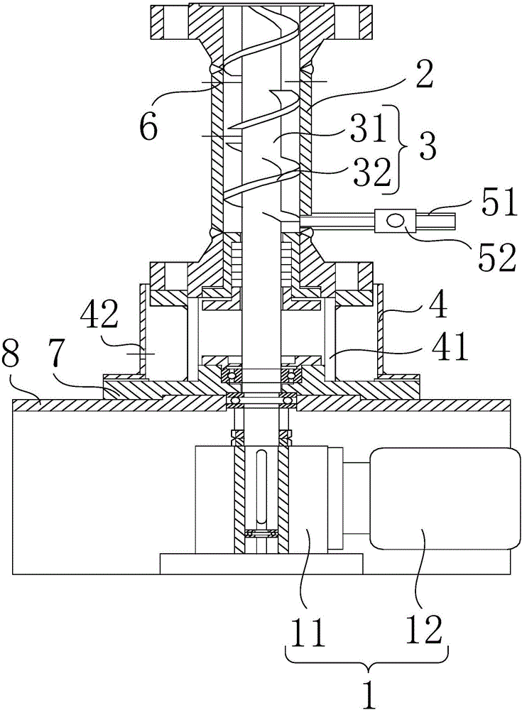
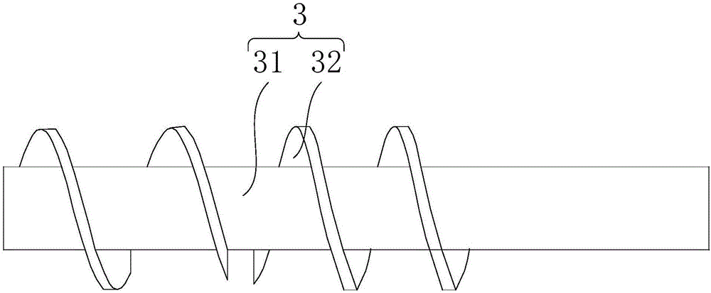
[0029] figure 1 Provide the structural representation of viscous material discharging device for the embodiment of the present invention, as figure 1 As shown, the viscous material discharge device provided by the embodiment of the present invention includes: a driving mechanism 1, a material delivery housing 2, an extrusion mechanism 3 and a stuffing chamber, and the material delivery housing 2 is provided with a material inlet and a material outlet , the stuffing chamber is connected with one end of the material delivery housing 2, the stuffing chamber is provided with a gas collecting part, the extruding mechanism 3 includes a shaft body 31 and a screw blade 32, the screw blade 32 is installed on the shaft body 31, and the shaft body 31 passes through The material delivery housing 2 is connected to the stuffing chamber and the driving mechanism 1 , the screw blade 32 is located in the material delivery housing 2 , and a first sealing member is arranged between the stuffing ...

Embodiment 2

[0046] The purpose of the second embodiment is to provide a viscous material manufacturing system to solve the technical problem of gas leakage during the viscous material discharge process in the prior art.

[0047] The viscous material production system provided in the second embodiment includes a reactor and the viscous material discharge device as in the above embodiment 1, and the feed port of the conveying shell 2 in the viscous material discharge device is connected to the reactor.

[0048] In the viscous material discharge device, a flange is provided at the feed port of the material conveying shell 2, and the material conveying shell 2 is connected with the discharge port of the reactor through the flange. The viscous material manufacturing system has the same advantages as the above-mentioned viscous material discharging device compared with the prior art, and will not be repeated here.

[0049] Specifically, the viscous material production system includes a modified...


PUM


Abstract

The invention provides a viscous and dense material discharging device and a viscous and dense material manufacturing system, and relates to the technical field of viscous and dense material production devices. The viscous and dense material discharging device comprises a driving mechanism, a material conveying shell, a squeezing mechanism and a padding chamber. The material conveying shell is provided with a material inlet and a material outlet, the padding chamber is connected with one end of the material conveying shell, the padding chamber is provided with a gas collecting part, the squeezing mechanism comprises a shaft and a spiral blade, the spiral blade is installed on the shaft, the shaft penetrates through the material conveying shell and the padding chamber and is connected with the driving mechanism, the spiral blade is located in the material conveying shell, and a first sealing element is arranged between the padding chamber and the shaft. The viscous and dense material discharging device is applied to the viscous and dense material production process so as to solve the technical problem of gas leakage in the viscous and dense material discharging process in the prior art.

Description

technical field [0001] The invention relates to the technical field of viscous material production devices, in particular to a viscous material discharging device and a viscous material manufacturing system. Background technique [0002] The viscous material is usually made in a reactor. After the reaction, there is gas and molten viscous material in the reactor. At the same time, there is still a lot of pressure in the reactor. During the discharging process of the viscous material, there is Part of the gas exists in the viscous material. When the material is discharged, the gas is mixed in the viscous material in the form of bubbles. When the viscous material is discharged, the gas inside will overflow, and the overflowing gas may contain harmful gas. thereby causing harm to the environment. Therefore, how to avoid gas leakage while discharging has become a technical problem to be solved urgently by those skilled in the art. Contents of the invention [0003] The objec...

Claims


Application Information

Patent Timeline
Patent Type & Authority Applications(China)
IPC IPC(8): B01J4/00B01J19/00B01J3/02B01J3/04
CPCB01J4/007B01J3/02B01J3/04B01J19/00B01J2204/005
Inventor 王珈乐
Owner 王珈乐
Why Eureka
Try Eureka