
Wafer transfer unit with blowdown function

A technology for conveying devices and wafers, applied in the directions of conveyor objects, transportation and packaging, cleaning methods and utensils, etc., can solve the problem that wafer conveying devices do not have a blowing function, etc., achieve good blowing effect and improve utilization rate , The effect of improving wafer yield

Inactive Publication Date: 2020-04-10
BRILLIAN NETWORK & AUTOMATION INTEGRATED SYST
View PDF5 Cites 0 Cited by
  • Summary
  • Abstract
  • Description
  • Claims
  • Application Information

AI Technical Summary

Problems solved by technology

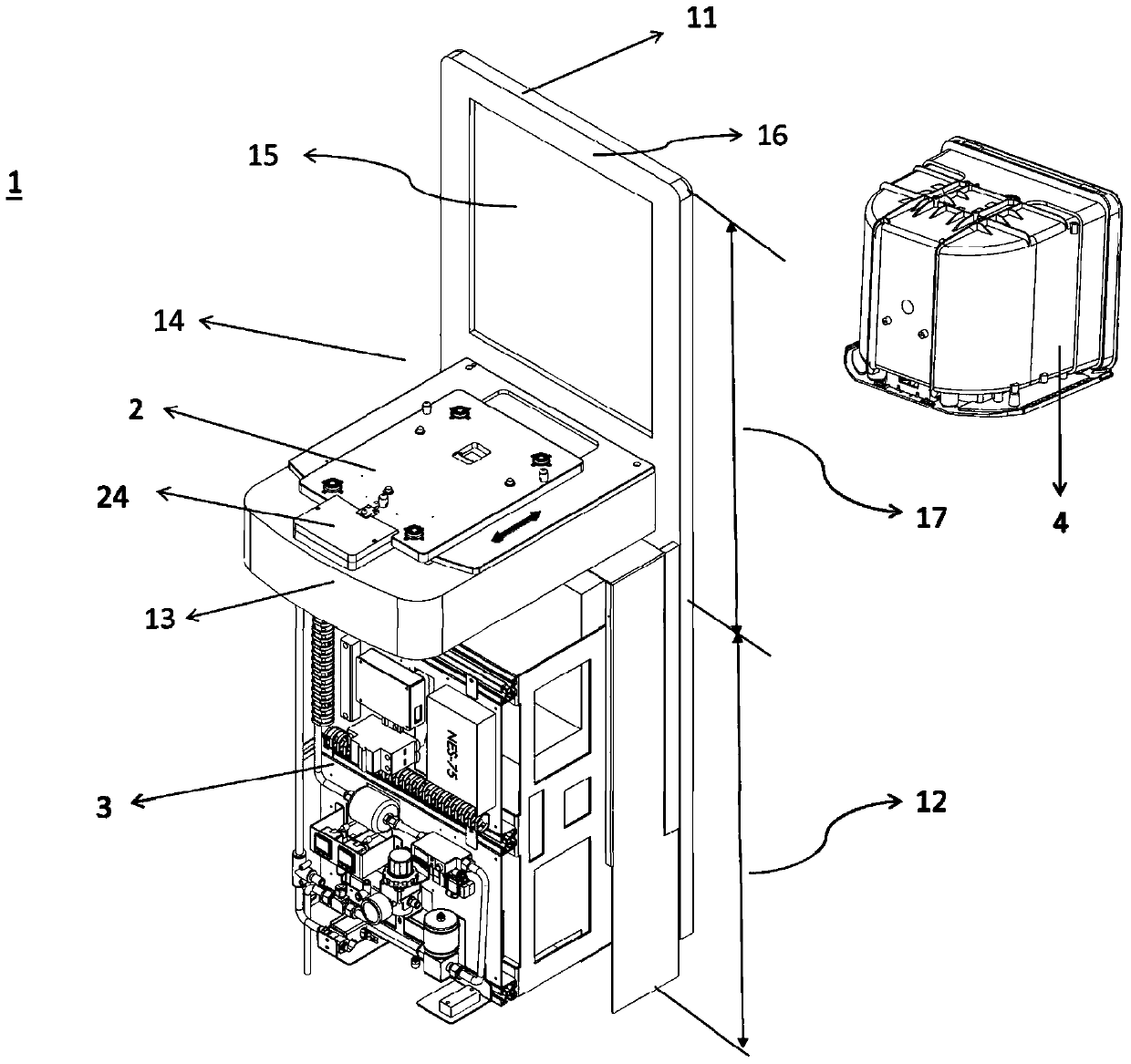
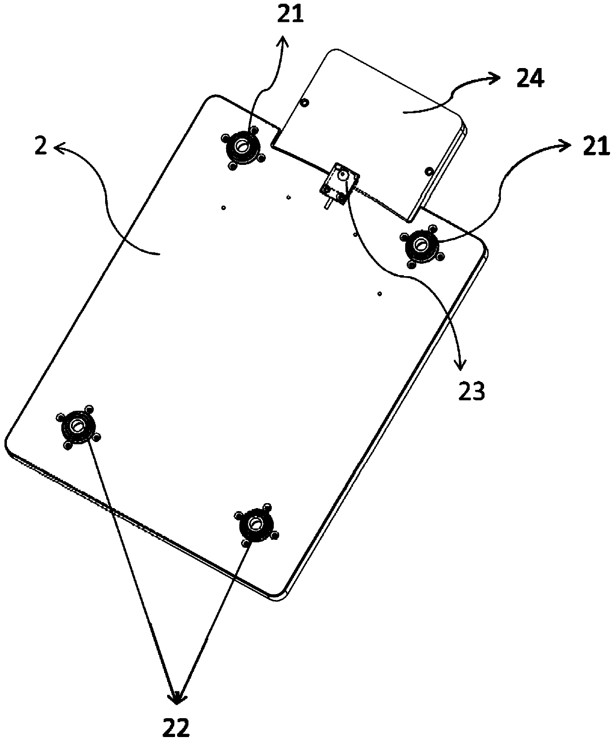
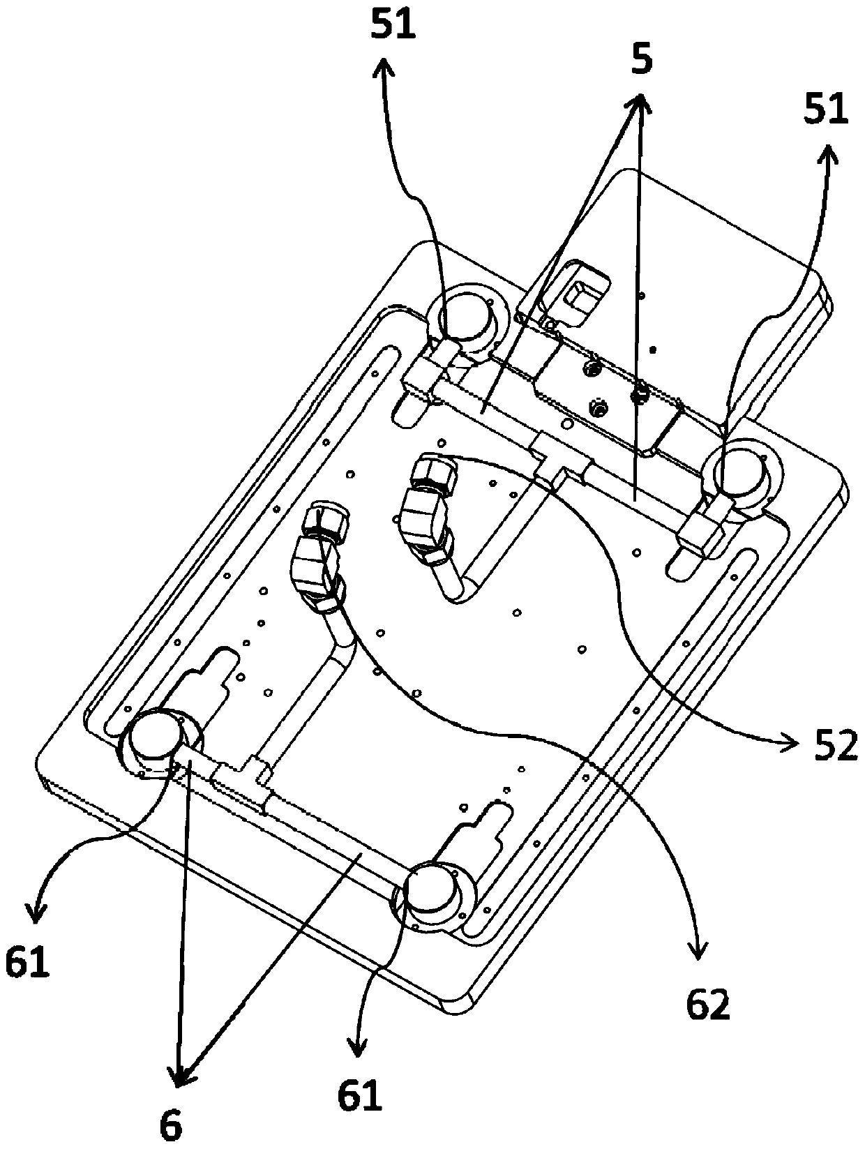
[0007] In order to solve the problem that the traditional wafer transfer device does not have the blowing function, the present invention provides a wafer transfer device with a blowing function. At least one blowing contact plate and a blowing The cleaning module, the wafer transfer device has a frame vertical to the ground, the blowing module is arranged on the lower half of the side of the frame, and a platform is formed on the top of the lower half, and the blowing contact plate is fixed on the On the platform part, and the frame is higher than the platform part to form an accommodating space, wherein, the blowing contact plate surface includes: at least one inflatable nozzle and at least one air outlet nozzle, which are arranged on the blowing contact plate surface, and both the inflating nozzle and the air outlet nozzle are connected with the blowing Module connection
[0009] In order to solve the problem that the traditional wafer transfer device identifies the type of front-loading wafer cassette, the present invention further provides a wafer transfer device with a blow-off function, which is to configure at least one blow-off contact disk surface in a wafer transfer device And a blowing module, the wafer transfer device has a frame vertical to the ground, the blowing module is arranged on the lower half of the side of the frame, and a platform is formed on the top of the lower half, and the contact disk surface is blown clean It is fixed on the platform part, and the frame is higher than the platform part to form an accommodating space, wherein, the blowing contact plate surface includes: at least one air charging nozzle and at least one air outlet nozzle, which are arranged on the blowing contact plate surface, and the air charging nozzle and the air outlet nozzle are both Connected with the blowing module; an identification device is arranged on the surface of the blowing contact plate. The identification device has an activated state, and through the actuation of the activated state, it is judged whether to start the blowing module to inflate or discharge air

Method used


Image

  • Wafer transfer unit with blowdown function
  • Wafer transfer unit with blowdown function
  • Wafer transfer unit with blowdown function

Examples


Embodiment Construction

[0018] The present invention discloses a wafer transfer device with a blow-off function. The techniques such as the mechanism processing of each component are already understood by those with ordinary knowledge in the relevant technical field, so a complete description will not be given in the following description. Meanwhile, the present invention will be described in detail below in conjunction with the accompanying drawings and specific embodiments. It should be noted that the drawings are all in a very simplified form and use imprecise ratios, which are only used to facilitate and clearly assist the purpose of illustrating the embodiments of the present invention.

[0019] First, see figure 1 , is a schematic structural diagram of the wafer transfer device according to an embodiment of the present invention. Such as figure 1 As shown, there is a frame 11 erected vertically on the ground in the wafer transfer device 1, and the frame 11 is further divided into a lower half...


PUM


Abstract

The invention relates to a wafer transmission device having a blowing-off function. At least one blowing-off contact disc surface and a blowing-off module are configured in the wafer transmission device, wherein each blowing-off contact disc surface comprises at least one inflation nozzle, at least one air outlet nozzle and an identification device, and the blowing-off module comprises an inflation inlet, an air outlet, at least one temperature / humidity sensor, at least one flow metering table and at least one pressure sensor. The wafer transmission device which does not possess a blowing-off technology possess the blowing-off technology after the blowing-off contact disc surface and the blowing-off module are configured, the problem of cleanness of a traditional wafer transmission device on a front opening unified pod is solved, and the wafer yield in a semiconductor process can be effectively improved.

Description

technical field [0001] The present invention relates to a wafer conveying device, especially a wafer conveying device (Load Port) used in a semiconductor process. Contamination inside the wafer cassette. Background technique [0002] The surface contamination control of wafers has become the primary task of semiconductor and other high-tech fabs, so as to improve the yield of wafers; Opening Unified Pod) is used as a device for storing and transporting wafers, so that large-sized wafers can be isolated from the outside air to avoid contamination of large-sized wafers. [0003] The wafer transfer device (Load Port) is used for carrying and opening the front-opening wafer box door between the front-opening wafer box and the semiconductor process equipment, so that the process equipment can obtain large-sized wafers for manufacturing . Since the door body of the front-loading wafer cassette is closed, the interior is in a partial vacuum state, so when the wafer transfer devi...

Claims


Application Information

Patent Timeline
Patent Type & Authority Patents(China)
IPC IPC(8): H01L21/677B08B5/02
CPCB08B5/02H01L21/677
Inventor 陈荣华古震维廖鸿文
Owner BRILLIAN NETWORK & AUTOMATION INTEGRATED SYST
Learn More