
Flange with hole and safety valve pressure test system based on flange with hole

A pressure test and safety valve technology, applied in the field of safety valves, can solve problems such as pipeline leakage, economic losses of factories and enterprises, personal injury, etc., and achieve the effects of increasing service life, accurate testing data, and convenient disassembly.

Active Publication Date: 2017-03-15
四川安测科技有限公司
View PDF8 Cites 2 Cited by
  • Summary
  • Abstract
  • Description
  • Claims
  • Application Information

AI Technical Summary

Problems solved by technology

[0003] When providing additional pressure to the medium inside the pipeline, it is necessary to ensure that the pressure equipment and the pipeline are completely sealed. Therefore, at present, the pressure equipment is often connected to the pipeline, and the pressure equipment is welded to the pipeline, which is not convenient for disassembly and maintenance of the pressure equipment. If the pressurized equipment leaks, the pipeline will also leak. Replacing the pipeline is equivalent to replacing the entire equipment, which increases the maintenance cost of the medium transportation equipment; the pressurized equipment cannot be disassembled repeatedly, on the one hand, it will shorten the use of the pressurized equipment On the one hand, it will weaken the air tightness and pressure bearing strength of the medium conveying pipeline, which will cause huge economic losses to factories and enterprises, and high pressure leakage will also cause serious personal injury

Method used


Image

  • Flange with hole and safety valve pressure test system based on flange with hole
  • Flange with hole and safety valve pressure test system based on flange with hole
  • Flange with hole and safety valve pressure test system based on flange with hole

Examples


Embodiment 1

[0033] Such as figure 1 As shown, a perforated flange of the present invention includes a flange 1, a hole 3 concentric and coaxial with the flange 1 is provided at the center axis of the flange 1, and a circumscribed flange 1 is provided on the side wall of the flange 1. Hole 2, the external connection hole 2 communicates with the channel 3.

[0034] The flange with external connection holes of the present invention is used for safety valve detection and verification in the fields of petroleum and natural gas industry, chemical industry, power plant, etc.; The pressure value in the pipeline system where the valve is located reaches the set pressure value of the safety valve, and whether the safety valve is qualified is judged by judging whether the safety valve is opened under the set pressure; The intermediate equipment of the pipeline system, the pressurized equipment is connected with the external hole of the flange, and the additional gas is passed into the hole of the f...

Embodiment 2

[0036] Such as figure 1 , figure 2 As shown, based on Embodiment 1, the flange 1 is a straight-through flange 4, and the through-hole 5 is opened on the straight-through flange 4, and the through hole 5 is equivalent to the tunnel 3.

[0037] The flange in the present invention adopts a straight-through flange, which is suitable for the safety valve pressure test system, where the safety valve is provided with a safety valve root valve, and the safety valve root has good air tightness. , directly install the straight-through flange between the safety valve and the root valve of the safety valve, and then connect the pressurizing equipment to the straight-through flange and communicate with the external connection hole to perform pressure testing on the safety valve; The invention uses the straight-through flange to detect the safety valve without stopping production. After the safety valve is tested, the safety valve can be disassembled or not. The straight-through flange is...

Embodiment 3

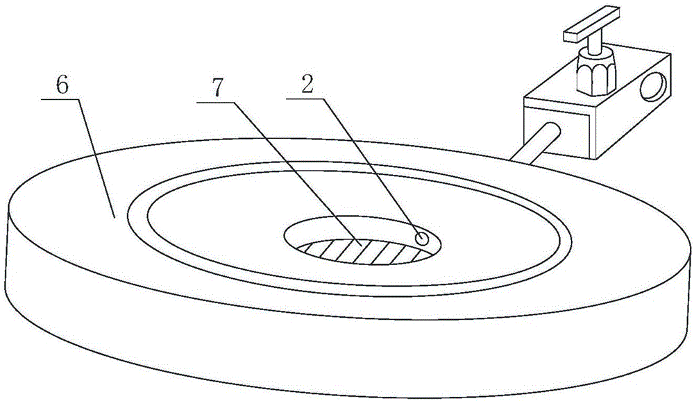
[0039] Such as figure 1 , image 3 As shown, based on Embodiment 1, the flange 1 is a blind plate 6, and a blind hole 7 is opened at the center of the blind plate 6, and the bottom of the blind hole 7 is closed, and the blind hole 7 is equivalent to the channel 3.

[0040] The present invention adopts a blind plate with an external connection hole as the intermediate connecting device between the pressurizing equipment and the safety valve pressure test system, and is suitable for the situation where the safety valve root valve is not installed at the lower end of the safety valve. In the safety valve pressure test system, there is no safety valve installed. The valve root valve has poor airtightness; the blind hole of the blind plate is the circulation channel of the pressurized gas, and the bottom of the blind hole is closed and has good airtightness, so the pressurized gas directly passes through the blind hole The safety valve can be used to detect the safety valve; the p...


PUM


Abstract

The invention discloses a flange with a hole and a safety valve pressure test system based on the flange with the hole. The flange with the hole comprises a flange plate. A duct concentric and coaxial with the flange plate is formed in the position of central axis of the flange plate. An external hole is formed in the side wall of the flange plate and communicates with the duct. By means of the beneficial effects that the flange is convenient to detach and install, the service life of the safety valve pressure test system is prolonged; a pressurization device communicates with a pipeline system in the safety valve pressure test system through the flange plate to conduct safety valve detection, and therefore the pressurization device can be repeatedly detached and installed, regulated overhaul and cleaning of the pressurization device in the safety valve pressure test system are achieved, the installation cost is further reduced, and the installation process is simplified. The gas tightness of the safety valve detection system cannot be influenced by installation and detachment of a pressurization system in the safety valve pressure test system based on the flange with the hole, and the detection result of the safety valve pressure test system is accurate.

Description

technical field [0001] The invention relates to the field of safety valves, in particular to a perforated flange and a safety valve pressure test system based on the perforated flange. Background technique [0002] The safety valve is a special valve whose opening and closing parts are in a normally closed state under the action of external force. When the medium pressure in the equipment or pipeline rises above the specified value, it discharges the medium to the outside of the system to prevent the medium pressure in the pipeline or equipment from exceeding the specified value. ;When the medium pressure value is higher than the specified value, the safety valve will automatically open, and the excess medium will be released to reduce the internal pressure. When the internal pressure value drops to the specified value, the safety valve will automatically close and the discharge will stop. Safety valves are automatic valves, mainly used in boilers, pressure vessels and pipel...

Claims


Application Information

Patent Timeline
Patent Type & Authority Applications(China)
IPC IPC(8): F16L23/00F16L23/032G01M13/00
CPCF16L23/006F16L23/032G01M13/00
Inventor 刘文敏王小东易爱民
Owner 四川安测科技有限公司
Learn More