
Dewatering and drainage system with detachable water collection tanks and dewatering and drainage method of dewatering and drainage system

A technology of drainage system and water collection tank, which is applied in the direction of construction and infrastructure engineering, etc., can solve the problems that cannot be moved and reused many times, large one-time investment, easy to crack and leak, etc., and achieves strong adaptability to the environment, short construction period, The effect of low maintenance cost

Active Publication Date: 2017-03-15
1ST ENG OF CHINA ZHONGTIE MAJORBRIDGE GROUP +1
View PDF7 Cites 1 Cited by
  • Summary
  • Abstract
  • Description
  • Claims
  • Application Information

AI Technical Summary

Problems solved by technology

At present, the water collection tank (pool) in the municipal precipitation system is generally formed by brick masonry, and its characteristic is that the water collection tank (pool) is for one-time use and cannot be moved and reused many times. Other pipelines require a large one-time investment, are prone to cracking and leakage during use, high maintenance costs, and long construction periods

Method used


Image

  • Dewatering and drainage system with detachable water collection tanks and dewatering and drainage method of dewatering and drainage system
  • Dewatering and drainage system with detachable water collection tanks and dewatering and drainage method of dewatering and drainage system
  • Dewatering and drainage system with detachable water collection tanks and dewatering and drainage method of dewatering and drainage system

Examples


Embodiment Construction

[0030] The present invention will be described in further detail below in conjunction with the accompanying drawings.

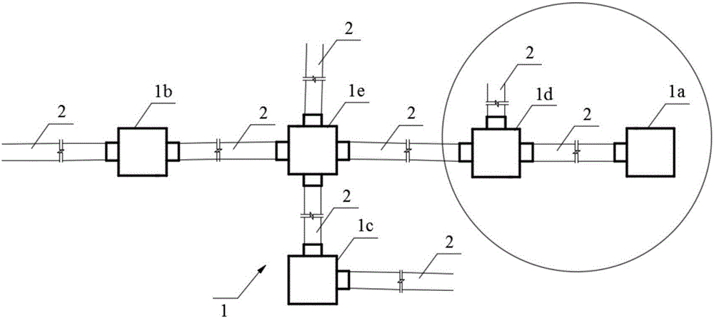
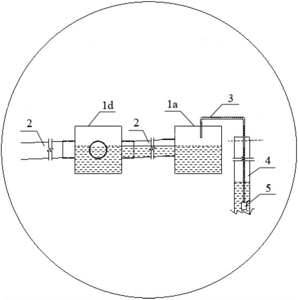
[0031] see figure 1 and figure 2 As shown, the present invention provides a dewatering drainage system provided with a detachable water collection box, which includes a water collection box group 1 , a drainage pipeline 2 , a downwater pipeline 3 , a water well 4 and a water pump 5 .

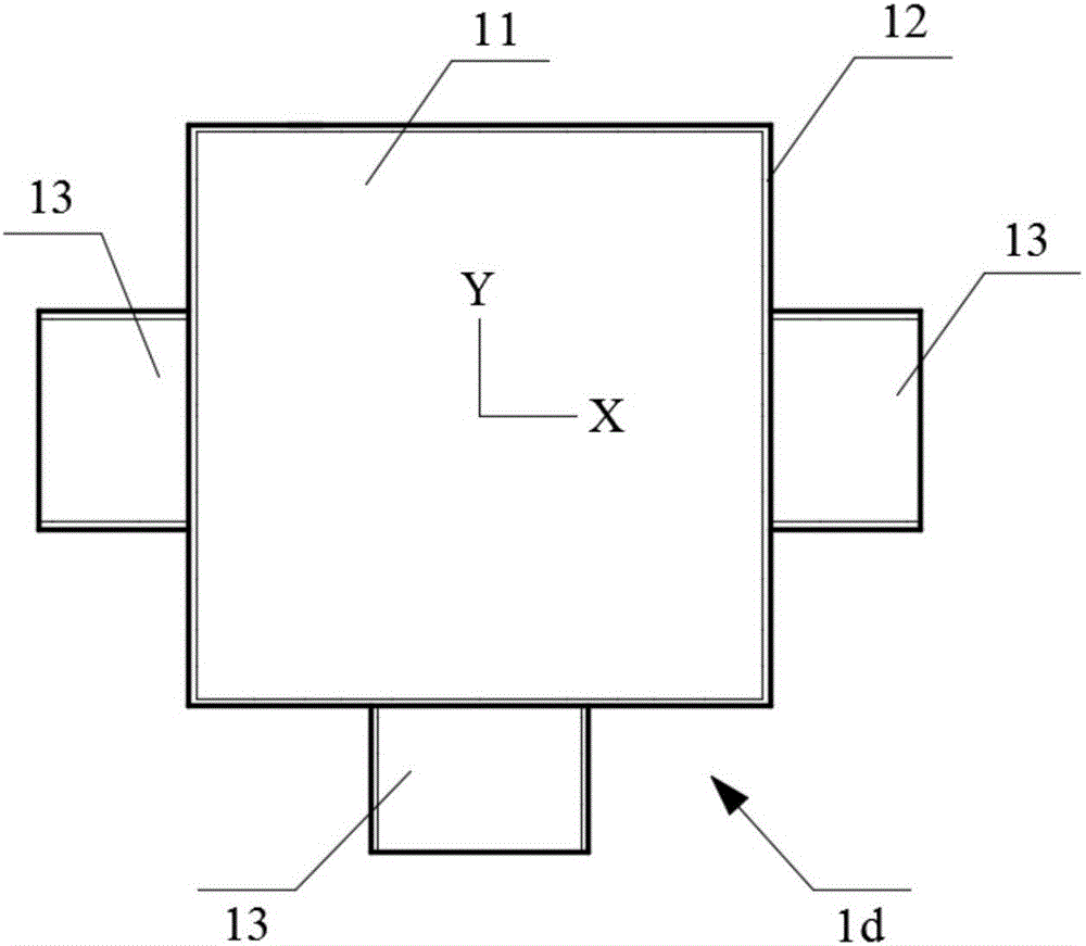
[0032] The water collection box group 1 includes a one-way water collection box 1a, a two-way straight-through water collection box 1b, a two-way corner water collection box 1c, a three-way water collection box 1d and a four-way water collection box 1e. The one-way water collection box 1a, the two-way straight-through water collection box 1b, the two-way corner water collection box 1c, the three-way water collection box 1d and the four-way water collection box 1e all include a bottom plate 11 and a cylindrical plate 12 fixed on the bottom plate 11. The bottom plate 11 and the...


PUM


Abstract

The invention discloses a dewatering and drainage system with detachable water collection tanks and a dewatering and drainage method of the dewatering and drainage system and relates to the field of municipal deep foundation pit dewatering and drainage construction. The dewatering and drainage system comprises a dewatering well, a water collection tank set, drainage pipes and a dewatering pipe. The water collection tank set comprises a one-way water collection tank, a two-way direct-connection water collection tank, a two-way corner water collection tank, a three-way water collection tank and a four-way water collection tank. Each of the one-way water collection tank, the two-way direct-connection water collection tank, the two-way corner water collection tank, the three-way water collection tank and the four-way water collection tank comprises a bottom plate and a cylindrical plate fixed to the bottom plate, each bottom plate and the corresponding cylindrical plate form a box-shaped structure without a cover. The cylindrical plates are all provided with holes and connector pipes arranged on the holes. The drainage pipes are detachably connected to the connector pipe. One end of the dewatering pipe is located in any one of the water collection tank set, the other end is located in the dewatering well, and the end portion of the end, located in the dewatering well, of the dewatering pipe is provided with a water pump. According to the dewatering and drainage system and method, the water collection tanks which can be detached and used repeatedly can be arranged flexibly according to the terrain environment, and the system is low in cost and high in adaptive capacity.

Description

technical field [0001] The invention relates to the field of municipal deep foundation pit drainage construction, in particular to a drainage system provided with a detachable water collection box and a drainage method thereof. Background technique [0002] At present, more and more large-scale underground structures are constructed using deep foundation pit drainage. The characteristics of municipal engineering are short construction period, tight time, small site and fast process change. The drainage system is a key project in the municipal deep foundation pit excavation project, and the water collection tank is the key link in the drainage system. Whether the setting is reasonable or not is related to the success or failure of the drainage system. At present, the water collection tank (pool) in the municipal precipitation system is generally formed by brick masonry, and its characteristic is that the water collection tank (pool) is for one-time use and cannot be moved an...

Claims


Application Information

Patent Timeline
IPC IPC(8): E02D19/10
CPCE02D19/10
Inventor 侯守飞王鹤周功建冯令才左阿龙陈浩
Owner 1ST ENG OF CHINA ZHONGTIE MAJORBRIDGE GROUP
Learn More