
Buffering device arranged in shock absorber

A technology of buffer device and shock absorber, applied in the direction of shock absorber, spring/shock absorber, shock absorber, etc. Guarantee the service life, improve work efficiency, and the effect of good use effect

Inactive Publication Date: 2017-03-08
YANGZHOU FOCUS SHOCK ABSORBER
View PDF0 Cites 0 Cited by
  • Summary
  • Abstract
  • Description
  • Claims
  • Application Information

AI Technical Summary

Problems solved by technology

[0003] The structure and defects of the existing built-in buffer device are as follows: 1) The upper end of the built-in spring is stuck on the working cylinder, and the lower end is suspended in the air. If the spring is not well done or the gap between the piston rod and the working cylinder is too small, it is easy to cause friction on the piston rod. noise;
[0004] 2) When the existing built-in spring is compressed and deformed, the working cylinder may be stretched open to cause oil leakage, resulting in unstable force value and empty travel;
[0005] 3) The existing built-in spring needs to be pressed into the working cylinder, and the installation is very time-consuming and laborious, which seriously affects the production efficiency

Method used


Image

  • Buffering device arranged in shock absorber
  • Buffering device arranged in shock absorber

Examples


Embodiment Construction

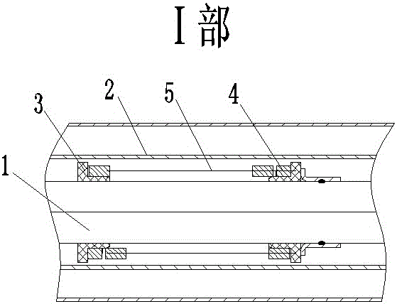
[0019] The present invention is arranged on the piston rod 1, between the piston rod 1 and the working cylinder 2, and includes sliding shoes 3 arranged at both ends of the piston rod 1, a spring 4 is arranged between the two sliding shoes 3, and one of the sliding shoes 3 is fixed Arranged on the piston rod 1 , another sliding shoe 3 can move along the piston rod 1 .

[0020] A guide sleeve 5 is sleeved on the outer side of the spring 4 .

[0021] The guide sleeve 5 includes a guide sleeve 1 51 and a guide sleeve 2 52 , wherein the guide sleeve 1 51 and the guide sleeve 2 52 are respectively fixed to the sliding shoes 3 on both sides.

[0022] The guide sleeves 5 of the present invention are arranged at both ends of the sliding shoe 3, because as long as the two ends of the spring 4 are restricted, the spring 4 will be effectively guided during the movement process, ensuring that the spring 4 can move smoothly and straightly during the movement process.

[0023] The sliding ...


PUM


Abstract

The invention relates to a buffering device arranged in a shock absorber. The buffering device is arranged on a piston rod (1) and located between the piston rod (1) and a working cylinder (2) and comprises sliding shoes (3) arranged at the two ends of the piston rod (1), a spring (4) is arranged between the two sliding shoes (3), one sliding shoe (3) is fixedly arranged on the piston rod (1), and the other sliding shoe (3) can move along the piston rod (1). After being provided with the two nylon sliding shoes, the buffering device can slide along the piston rod smoothly, rod friction can be avoided, and noise can be avoided.

Description

technical field [0001] The invention relates to a shock absorber built-in buffer device, which is applied to the technical field of shock absorbers. Background technique [0002] The shock absorber is divided into an upper chamber and a lower chamber, wherein a piston rod is arranged in the upper chamber, and a buffer device is arranged in the upper chamber, and its function is to absorb energy and buffer before the shock absorber is stretched to the limit. [0003] The structure of the existing built-in buffer device and its defects are: 1) The upper end of the built-in spring is stuck on the working cylinder, and the lower end is suspended. If the spring is not well done or the gap between the piston rod and the working cylinder is too small, friction on the piston rod will easily occur. noise; [0004] 2) When the existing built-in spring is compressed and deformed, the working cylinder may be stretched to produce oil leakage, resulting in unstable force value, idle stro...

Claims


Application Information

Patent Timeline
Patent Type & Authority Applications(China)
IPC IPC(8): F16F9/32
Inventor 李凯许雁南孙薇谈磊
Owner YANGZHOU FOCUS SHOCK ABSORBER
Learn More