
Assembling-type beam-column hinged node and assembling mode thereof

A prefabricated, beam-column technology, applied in the direction of architecture, building structure, etc., can solve the problems of complex beam-column joint connection structure, no obvious advantages and progress, and inconvenient wet operation, so as to shorten the assembly construction period and have strong versatility , Reduce the effect of dirty construction environment

Inactive Publication Date: 2017-03-08
SICHUAN CHINA STRUCTURE RESIDENTIAL IND
View PDF11 Cites 4 Cited by
  • Summary
  • Abstract
  • Description
  • Claims
  • Application Information

AI Technical Summary

Problems solved by technology

The existing prefabricated prefabricated beam-column node connection technology prefabricates each layer of columns, and then combines prefabricated beams and prefabricated slabs, and finally casts in-situ nodes; Restricted by factors such as operation, complex construction, labor cost, and construction period, there is no obvious advantage and progress compared with the traditional beam-column connection technology, and the existing prefabricated beam-column connection technology makes the beam-column joint connection structure complex, It brings great inconvenience to wet work, and construction defects such as honeycomb pockmarks are easy to appear

Method used


Image

  • Assembling-type beam-column hinged node and assembling mode thereof
  • Assembling-type beam-column hinged node and assembling mode thereof
  • Assembling-type beam-column hinged node and assembling mode thereof

Examples


Embodiment 1

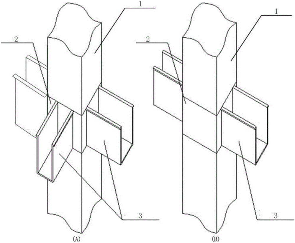
[0036] Such as figure 1 As shown in (B), the prefabricated beam-column joints, including figure 1 As shown in (B), the prefabricated beam-column hinge joint includes prefabricated column 1 and prefabricated beam 4; prefabricated column 1 is provided with hoop 2, and hoop 2 is provided with two U-shaped connecting plates 3; two U-shaped The shaped connecting plate 3 makes the nodes of the beam-column connection form a triangular stable structure, which increases the stability of the beam-column connection.

[0037] The prefabricated column 1 is a square column, and the prefabricated column 1 is installed with the ferrule 2 and two U-shaped connecting plates 2 after prefabrication.

[0038] The U-shaped connecting plate 3 is fixedly connected with the outer surface of the ferrule 2 where it is located.

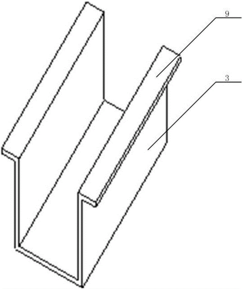
[0039] Such as figure 2 As shown, the U-shaped connecting plate 3 is provided with a U-shaped connecting plate edge 9 .

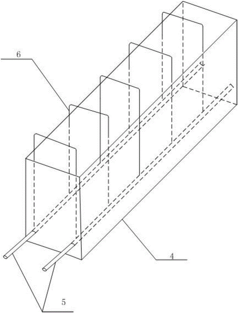
[0040] Such as image 3 As shown, the prefabricat...

Embodiment 2

[0053] Such as figure 1 As shown in (A), the prefabricated beam-column joints, including figure 1 As shown in (B), the prefabricated beam-column hinge joint includes prefabricated column 1 and prefabricated beam 4; prefabricated column 1 is provided with hoop 2, and hoop 2 is provided with three U-shaped connecting plates 3; three U-shaped The connecting plate 3 can be used for the beam-to-column connection of the edge part of the building body.

[0054] The prefabricated column 1 is a square column, and the prefabricated column 1 is installed with the ferrule 2 and three U-shaped connecting plates 2 after prefabrication.

[0055]The U-shaped connecting plate 3 passes through the hoop 2 where it is located, and one end thereof is located inside the prefabricated column 1 .

[0056] Such as figure 2 As shown, the U-shaped connecting plate 3 is provided with a U-shaped connecting plate edge 9 .

[0057] Such as image 3 As shown, the prefabricated beam 4 includes a beam bo...


PUM


Abstract

The invention provides an assembling-type beam-column hinged node and an assembling mode thereof. The problems that in the prior art, construction is complex, the labor cost is high, the construction period is long, and a construction site is dirty, disorderly and bad are solved, and meanwhile the problems that in the prior art, joint construction is complex, and construction defects are prone to appearance are solved. The assembling-type beam-column hinged node comprises a prefabricated column, a prefabricated beam, a hoop, U-shaped connecting plates, an upper beam reinforcing steel bar and the like. The prefabricated beam comprises a beam body, inner stirrups and a lower beam reinforcing steel bar; outer stirrups are arranged in the U-shaped connecting plates. According to the assembling-type beam-column hinged node and the assembling mode thereof, the prefabricated column, the prefabricated beam and a laminated slab are organically combined, it is reduced that the construction environment is dirty, disorderly and bad in the prior art; meanwhile, the prefabricated column only needs to be installed and positioned, the structure assembling rate is increased, the assembling construction period is shortened, and the construction cycle is shortened; the assembling-type beam-column hinged node has the advantages of being specific in stress, high in universality, low in cost, easy and convenient to construct and the like, and it can be better embodied that the advantages of a prefabricated assembling-type building is good in energy saving effect, environmentally friendly, efficient and the like.

Description

technical field [0001] The invention belongs to the field of architectural design and construction, and relates to an architectural design and its assembly method, in particular to an assembled beam-column hinge joint and its assembly method. Background technique [0002] The beam-column joint is the common part of the beam-column components of the frame. The failure of the joint means that the beams and columns connected to it will fail at the same time, which will seriously cause the entire frame to collapse. The existing prefabricated prefabricated beam-column node connection technology prefabricates each layer of columns, and then combines prefabricated beams and prefabricated slabs, and finally casts in-situ nodes; Restricted by factors such as operation, complex construction, labor cost, and construction period, there is no obvious advantage and progress compared with the traditional beam-column connection technology, and the existing prefabricated beam-column connecti...

Claims


Application Information

Patent Timeline
Patent Type & Authority Applications(China)
IPC IPC(8): E04B1/21
CPCE04B1/21
Inventor 车大桥邹阳成小冬胡鑫陈洪令
Owner SICHUAN CHINA STRUCTURE RESIDENTIAL IND
Learn More