LED lamp using switching circuit

A technology of LED lamps and switching circuits, which is applied in the layout of electric lamp circuits, the use of semiconductor lamps, electric light sources, etc. It can solve problems such as connection failure, power supply, and inability to stabilize LED lamps, so as to improve working characteristics and improve the function of preventing electric shocks Effect

Active Publication Date: 2017-02-22
AMOSENSE
View PDF6 Cites 9 Cited by
  • Summary
  • Abstract
  • Description
  • Claims
  • Application Information

AI Technical Summary

Problems solved by technology

However, a problem with LED lights using mechanical switches is that connection failure may occur depending on the degree of vibration and coupling, and thus it may not be possible to stably power the LED lights

Method used


Image

  • LED lamp using switching circuit
  • LED lamp using switching circuit
  • LED lamp using switching circuit

Examples


Embodiment Construction

[0028] Hereinafter, preferred embodiments of the present invention are described with reference to the accompanying drawings in order to describe the present invention in detail so that those skilled in the art related to the present invention can easily practice the present invention. It should be noted that like reference numerals are used throughout the drawings to designate like or similar elements. In the following description of the present invention, detailed descriptions of known functions and configurations that are considered to obscure the subject matter of the present invention will be omitted.

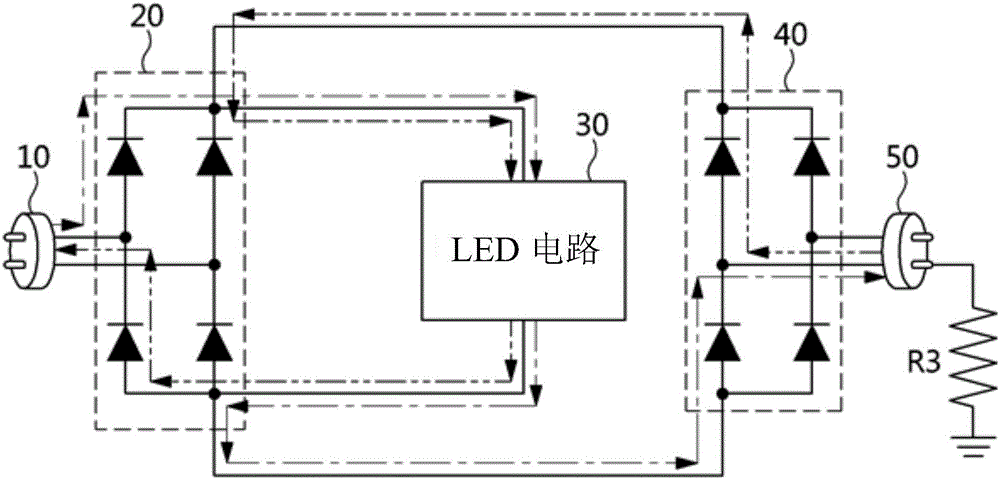
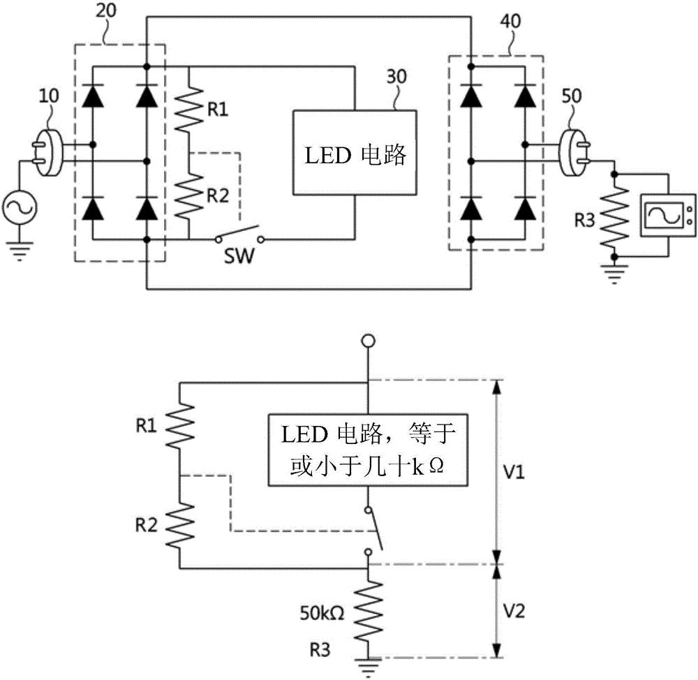
[0029] figure 1 is the view used to describe a common LED lamp, and figure 2 is a view used to describe a conventional LED lamp using an electronic circuit. Figure 4 to Figure 6 is a view for describing an LED lamp using a switching circuit according to an embodiment of the present invention.

[0030] Such as figure 1 As shown, the LED lamp is configured to include a...


PUM


Abstract

Provided is an LED lamp using a switching circuit, which prevents an electric shock caused by contact with a human body or conductive metal by arranging the switching circuit between a first rectifier circuit and an LED circuit. The LED lamp using the switching circuit connects the switching circuit to at least one line among a plurality of lines connecting the rectifier circuit and LED circuit. The switching circuit includes: a switching device including at least one among an SCR, a TRIAC, a TR, and a FET; and a driving device including at least one among a condenser, a TVS, a SIDAC, a resistor, and an inductor.

Description

technical field [0001] The present invention generally relates to an LED lamp using a switching circuit, and more particularly, to an LED lamp using a switching circuit for preventing electric shock caused by contact of a human body with the LED lamp when installing the LED lamp. [0002] This application claims the rights and interests of the Korean patent application No. 10-2014-0043170 with the filing date of April 10, 2014 and the Korean patent application with the application number 10-2014-0101874 with the filing date of August 7, 2014, and patent The entire content of the application is hereby incorporated by reference into this application. Background technique [0003] In general, fluorescent lamps that are energy-saving and have high luminous intensity have been used as lighting equipment for houses, buildings, factories, and the like. A fluorescent lamp is a lighting device that operates in such a way that a high voltage therein causes a discharge and ultraviolet...

Claims


Application Information

Patent Timeline
Patent Type & Authority Applications(China)
IPC IPC(8): H05B33/08H05B37/02H05B44/00
CPCF21Y2115/10F21V25/02Y02B20/30H05B47/10H05B45/59
Inventor 罗元蒜朴晋杓韩普铉韩澈承
Owner AMOSENSE
Why Eureka
Try Eureka