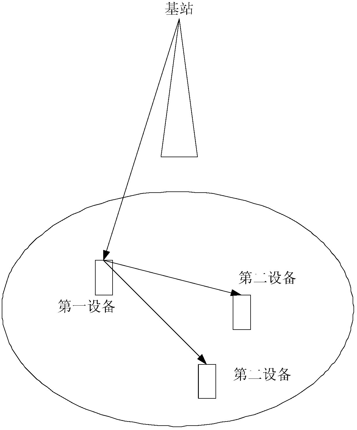
Method, device and system for transmitting data
A technology for transmitting data and equipment, which is applied in the field of equipment and systems, a method of transmitting data, and can solve problems such as small frequency diversity gain
- Summary
- Abstract
- Description
- Claims
- Application Information
AI Technical Summary
Problems solved by technology
Method used
Image
Examples
Embodiment 1
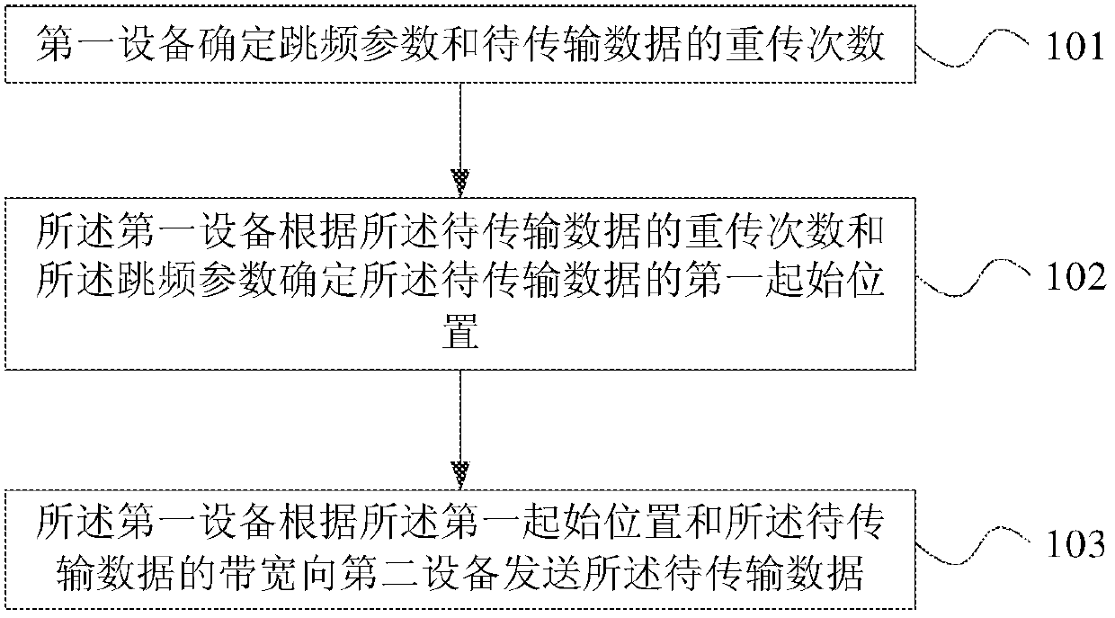
[0183] If the current retransmission subframe belongs to the first time subset, the first device determines a first start position of the data to be transmitted according to the initial frequency hopping position and the total frequency hopping bandwidth;
[0184] If the current retransmission subframe belongs to the second time subset, the first device determines the first time interval of the data to be transmitted according to the initial position of the frequency hopping, the bandwidth of the data to be transmitted, and the total bandwidth of the frequency hopping start position.
[0185] For example, the algorithm of formula (1) can be used to determine the first starting position of the data to be transmitted,
[0186]
[0187] Among them, n VRB,1 , n VRB,2 Respectively represent the starting positions of the data to be transmitted in the low-frequency band and high-frequency band in the frequency domain, which can be determined by the initial position of the frequenc...
Embodiment 2
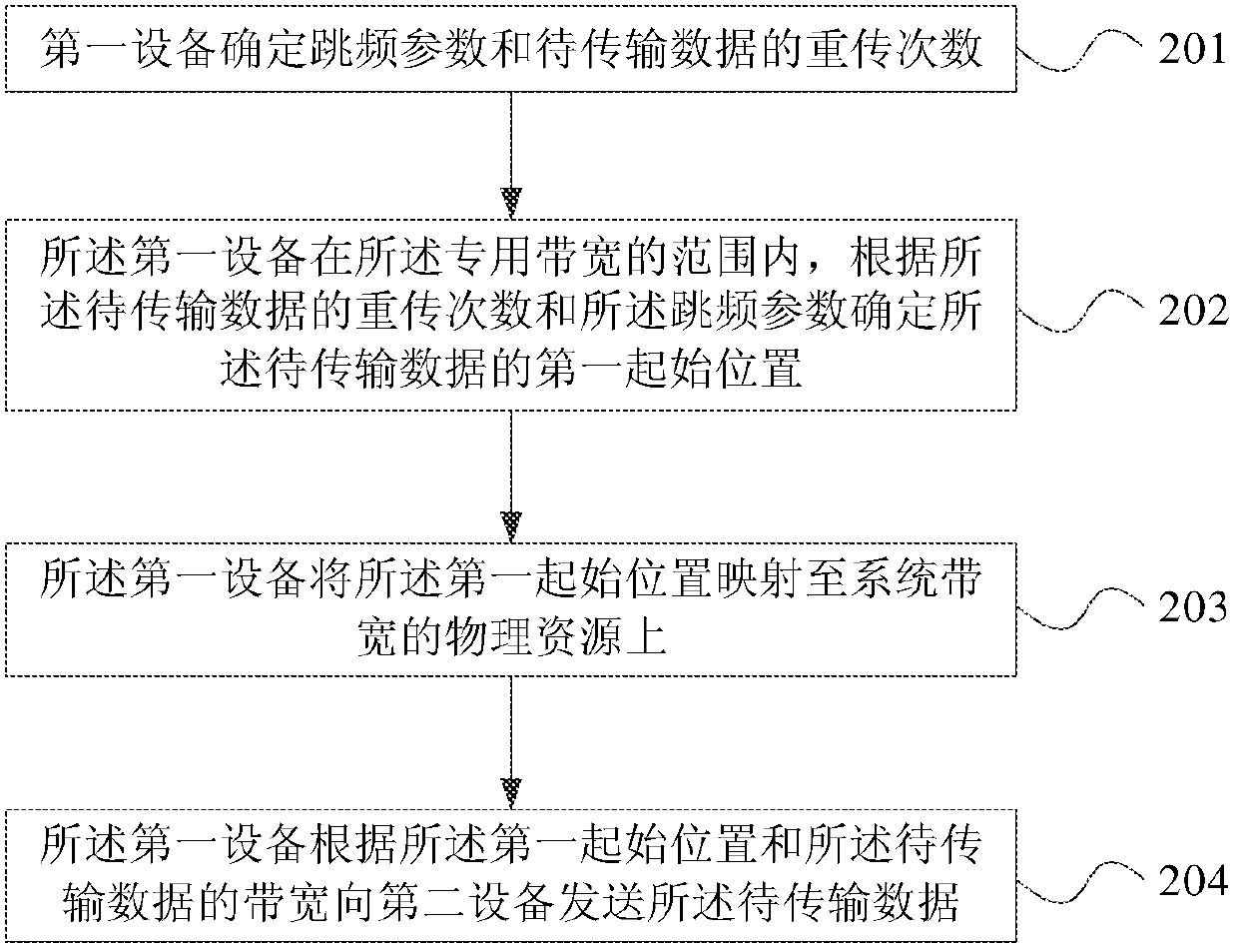
[0194] If the current retransmission subframe belongs to the first time subset, the first device moves from a lower frequency position to a higher frequency position according to the initial frequency hopping position, the bandwidth of the data to be transmitted, and the total frequency hopping bandwidth , and the product of the number of retransmissions and the frequency hopping offset, to determine the first starting position of the data to be transmitted;
[0195] If the current retransmission subframe belongs to the second time subset, the first device moves from a higher-frequency position to a lower-frequency position according to the initial frequency hopping position, the bandwidth of the data to be transmitted, and the total frequency hopping bandwidth , and the product of the number of retransmissions and the frequency hopping offset to determine the first starting position of the data to be transmitted.
[0196] For example, the algorithm of formula (2) can be used ...
Embodiment 3
[0216] If the maximum number of retransmissions is not greater than 2, and the current retransmission subframe belongs to the first time subset, then the first device determines the first starting time according to the initial frequency hopping position and the total frequency hopping bandwidth Location;
[0217] If the maximum number of retransmissions is not greater than 2, and the current retransmission subframe belongs to the second time subset, the first device, according to the initial frequency hopping position, the bandwidth of the data to be transmitted, and the frequency hopping the total bandwidth determines said first starting position;
[0218] If the maximum number of retransmissions is greater than 2, and the current retransmission subframe belongs to the first time subset, the first device moves from a lower frequency position to a higher frequency position according to the frequency hopping initial position, The bandwidth of the data to be transmitted, the to...
PUM
 Abstract
Description
Claims
Application Information
 - R&D
- Intellectual Property
- Life Sciences
- Materials
- Tech Scout
- Unparalleled Data Quality
- Higher Quality Content
- 60% Fewer Hallucinations
Browse by: Latest US Patents, China's latest patents, Technical Efficacy Thesaurus, Application Domain, Technology Topic, Popular Technical Reports.
© 2025 PatSnap. All rights reserved.Legal|Privacy policy|Modern Slavery Act Transparency Statement|Sitemap|About US| Contact US: help@patsnap.com


