Optical film and optical laminate using same

An optical laminate and optical film technology, which is applied in the field of optical films, can solve the problems of increased light leakage from polarizing elements, decreased polarization degree, and reduced function of polarized sunglasses, and achieves the effect of maintaining metallic tone and suppressing the decrease in polarization degree.

Active Publication Date: 2017-02-22
NIPPON KAYAKU CO LTD +2
View PDF10 Cites 8 Cited by
  • Summary
  • Abstract
  • Description
  • Claims
  • Application Information

AI Technical Summary

Problems solved by technology

[0014] As mentioned above, when the cholesteric liquid crystal layer is used, a metallic tone can be imparted without using a multilayer film, but on the other hand, in principle, the transmitted light in the reflection wavelength region is circularly polarized light, and when combined with a polarizing element, the following novelty occurs: The problem: the polarizing element cannot sufficiently absorb the transmitted light, and the leaked light from the polarizing element increases, which reduces the original function of polarized sunglasses
According to Patent Document 1, the cholesteric liquid crystal layer uses only one layer of right-handed helical alignment, and so far, there is no effective solution to the above-mentioned problem of lowering the degree of polarization.

Method used


Image

  • Optical film and optical laminate using same
  • Optical film and optical laminate using same
  • Optical film and optical laminate using same

Examples


Embodiment 1

[0079]

[0080] Using the prepared coating liquids (R1) and (L1), a light reflection layer was produced in the following procedure, and then these were laminated to produce a laminate of the light reflection layer used in the present invention. As the plastic substrate, a PET film (without undercoat layer) manufactured by Toyobo Co., Ltd. was used.

[0081] (1) Each coating solution was coated on a PET film at room temperature using a wire bar so that the film thickness after drying was 4 μm.

[0082] (2) Heating at 150° C. for 5 minutes removes the solvent and forms a cholesteric liquid crystal phase. Next, a high-pressure mercury lamp (manufactured by Harison Toshiba Lighting Co., Ltd.) was output at 120 W, and UV was irradiated for 5 to 10 seconds to fix the cholesteric liquid crystal phase and obtain a light reflection layer.

[0083] (3) The light reflection layer side mutual of the light reflection layer (R1) and the light reflection layer (L1) produced in (1)-(2) wer...

Embodiment 2

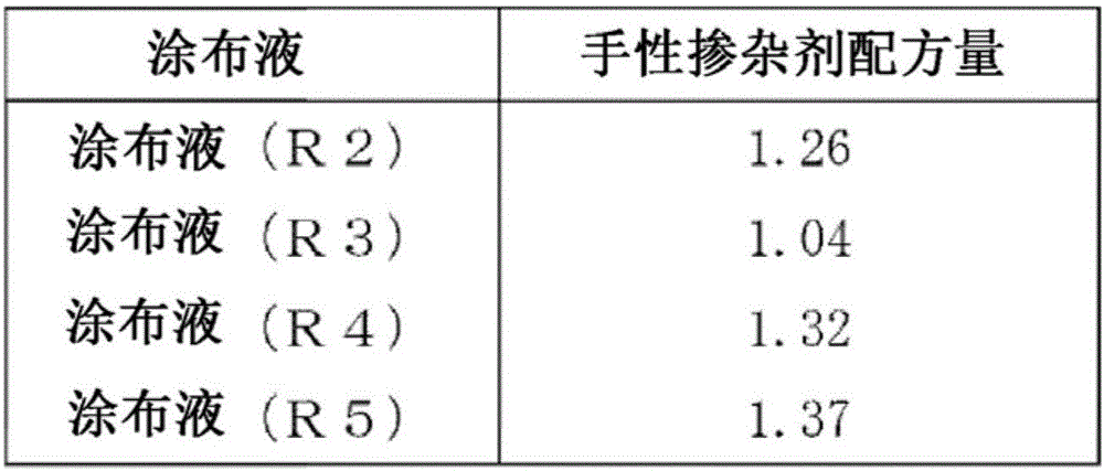
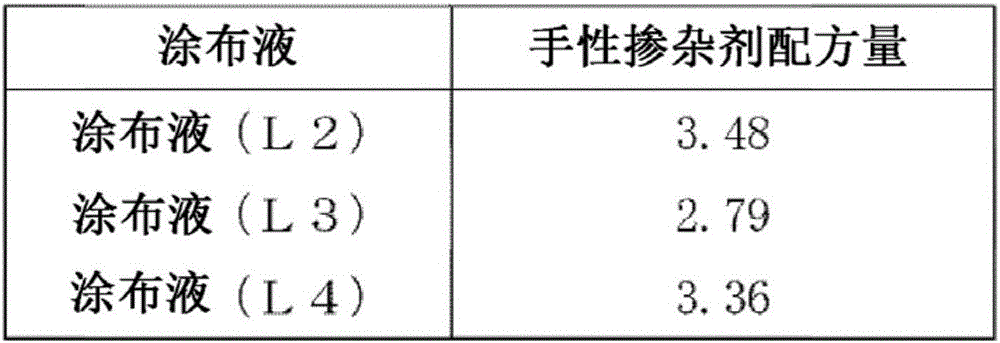
[0095] Except having used the prepared coating liquid (R2), (L2), it carried out similarly to Example 1, and obtained the laminated body of the light reflection layer used for this invention. Both the central reflection wavelengths of the light reflection layer ( R2 ) and the light reflection layer ( L2 ) were 540 nm. Next, a polarizing element was laminated in the same manner as in Example 1 to obtain the optical film of the present invention. The polarization degree of this optical film was measured by the same operation as Example 1, and the polarization degree was 98.1%.

Embodiment 3

[0097] Except having used the prepared coating liquid (R3), (L3), it carried out similarly to Example 1, and obtained the laminated body of the light reflection layer used by this invention. The central reflection wavelengths of the light reflection layer ( R3 ) and the light reflection layer ( L3 ) were 650 nm and 630 nm, respectively. Next, a polarizing element was laminated in the same manner as in Example 1 to obtain the optical film of the present invention. The polarization degree of this optical film was measured by the same operation as Example 1, and the polarization degree was 98.3%.


PUM

PropertyMeasurementUnit
visible light transmittanceaaaaaaaaaa
glass transition temperatureaaaaaaaaaa

Abstract

[Problem] The present invention provides eyewear, such as polarized sunglasses, having cholesteric liquid crystal layers, wherein the eyewear has a metallic tone and antiglare properties, minimizes the reduction in light-polarizing element absorptive capability that is associated with circular polarization, and is moreover unaffected by external degrading factors such as sebum, moisture, and salt air. [Solution] This optical film is characterized by being provided with a light-reflecting layer R comprising a cholesteric liquid crystal layer that has right-handed helical orientation, a light-reflecting layer L comprising a cholesteric liquid crystal layer that has left-handed helical orientation, and a polarizing element layer.

Description

technical field [0001] The present invention relates to an optical film mainly used for eyeglasses (sunglasses, safety glasses, helmet goggles, etc.) provided with a light reflection layer and a polarizing element that reflect visible light. Background technique [0002] To reduce glare caused by reflected light from water, roads, snow, etc., use glasses (sunglasses, protective glasses, goggles, etc.). For example, the lenses of sunglasses are colored with pigments, and the absorption of the pigments reduces the amount of light incident on the eyes, thereby reducing glare. Polarized sunglasses are particularly effective for reflected light from water and snow. [0003] In polarized sunglasses, since the reflected light is polarized, by designing it to effectively absorb light in this polarized direction, it is possible to greatly reduce the amount of incident light to the eyes, reduce glare, and improve visibility. [0004] Polarized sunglasses usually have a structure in w...

Claims


Application Information

Patent Timeline
Patent Type & Authority Applications(China)
IPC IPC(8): G02B5/30B32B7/02G02C7/10G02C7/12
CPCG02C7/10G02C7/12G02B5/3016G02B5/3041G02B5/30G02B27/288G02C7/108
Inventor 田中兴一矢作悦幸藤泽秀好后藤拓也村井克之光畑和久中村恭介
Owner NIPPON KAYAKU CO LTD
Why Eureka
Try Eureka