Fuel pump assembly and method for operating a similar assembly

A fuel pump and fuel technology, applied in combustion methods, fuel heat treatment devices, fuel supply, etc., can solve the problem of reduced or at least partial or even complete delivery volume, achieve reliable and precise manipulation, and improve delivery behavior.

Active Publication Date: 2019-06-07
ROBERT BOSCH GMBH
View PDF9 Cites 0 Cited by
  • Summary
  • Abstract
  • Description
  • Claims
  • Application Information

AI Technical Summary

Problems solved by technology

When operating such a fuel pump assembly with hot fuel, the delivery volume may drop or at least partially, or even completely

Method used


Image

  • Fuel pump assembly and method for operating a similar assembly
  • Fuel pump assembly and method for operating a similar assembly

Examples


Embodiment Construction

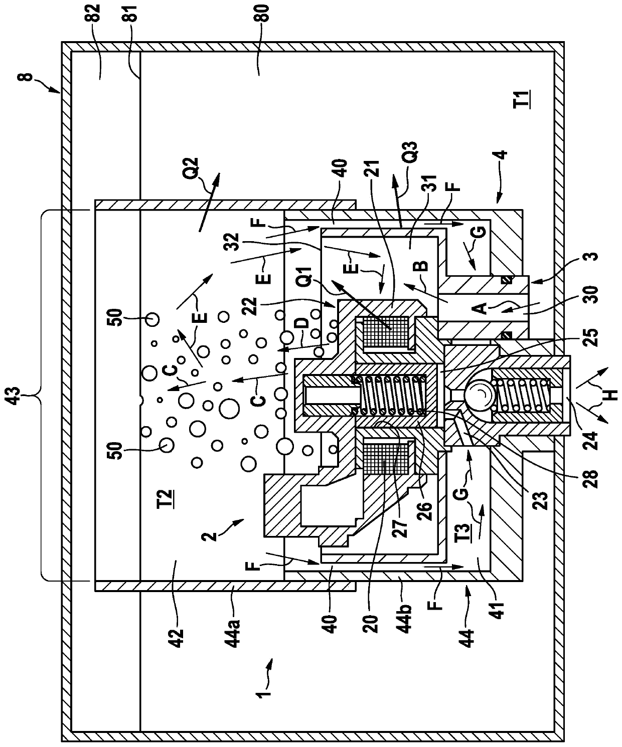
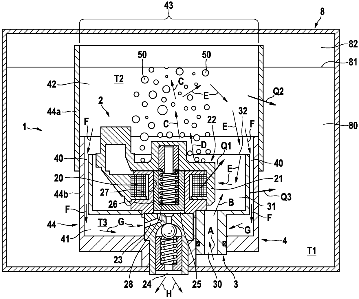
[0018] Next refer to figure 1 A fuel pump assembly 1 according to a preferred embodiment of the present invention is explained in detail.

[0019] As is evident from the single drawing, the fuel pump assembly 1 according to the invention has a fuel pump 2 , a first housing 3 and a second housing 4 . Furthermore, the fuel pump assembly 1 is arranged in a fuel tank 8 of a vehicle which is not shown. The fuel tank 8 has a fuel area 80 and an air or vapor area 82 , wherein the fuel level is indicated by a line 81 .

[0020] The fuel pump 2 as an electromagnetic piston pump has a pump housing 22 with an inlet channel 23 and an outlet channel 24 , a delivery chamber 25 , a piston 26 movable in a cylinder chamber 27 , a heat-generating actuator 20 and a spring element 28 . The fuel pump 2 is arranged such that the fuel pump 2 is arranged partly in the first housing 3 and partly in the second housing 4 . In particular, the heat-generating actuator 20 as a solenoid coil is located i...


PUM


Abstract

The present invention relates to a fuel pump arrangement (1) which comprises a fuel pump (2) which has a heat-generating actuator (20) which is arranged in a housing region (21) of a pump housing (22), characterized by: a first housing (3) which has a fuel inlet (30) which leads to a first fuel receiving chamber (31), in which the housing region (21) of the pump housing (22) is arranged, and a first outlet opening (32), wherein the actuator (20) outputs heat to the fuel situated in the first fuel receiving chamber, and a second housing (4) which surrounds the first housing (3) and, with the first housing (3), delimits a connecting opening (40) which connects the first fuel receiving chamber (31) to a second fuel receiving chamber (41) of the second housing (4), which second fuel receiving chamber (41) is flow-connected, furthermore, to an inlet duct (23) of the fuel pump (2). The present invention further relates to a method for operating a fuel pump arrangement (1) according to the invention.

Description

technical field [0001] The invention relates to a fuel pump assembly for a fuel vehicle, in particular a motorcycle, and to a method for operating such a fuel pump assembly. Furthermore, the invention relates to a fuel tank comprising such a fuel pump assembly and a fuel vehicle comprising such a fuel tank. Background technique [0002] Such a fuel pump assembly and such a method are known for example from GB 2478876A. This is a fuel pump, in particular an electromagnetic piston pump, with an inlet and an outlet, wherein the inlet is arranged inside the fuel tank and the outlet is arranged outside the fuel tank. Fuel is sucked from the fuel tank into the fuel pump via the inlet and delivered to the internal combustion engine via the outlet. When operating such a fuel pump assembly with hot fuel, the delivery volume may drop or at least partially, or even completely. The reason for this is that when drawing in hot fuel close to its boiling point it is possible that the dra...

Claims


Application Information

Patent Timeline
Patent Type & Authority Patents(China)
IPC IPC(8): F02M37/10F02M37/14F02M37/22F02M31/125
CPCF02M31/125F02M37/106F02M37/14F02M37/30F23K5/04F23K5/142Y02T10/12
Inventor S·芙洛F·尼切T·阿尔盖尔A·普利施A·古切尔A·克鲁舍W·莫伊雷尔
Owner ROBERT BOSCH GMBH
Why Eureka
Try Eureka