Thermoforming apparatus

A thermoforming and hot plate technology, applied in the direction of coating, etc., can solve the problems of loss of air outflow space, flake blockage due to softening of vacuum holes, uneven heating of flakes, etc., and achieve the effect of suppressing quality degradation and reducing imprinting

Inactive Publication Date: 2017-02-22
ASANO LABORATORIES CO LTD
View PDF3 Cites 2 Cited by
  • Summary
  • Abstract
  • Description
  • Claims
  • Application Information

AI Technical Summary

Problems solved by technology

However, the vacuum holes may become clogged with softened flakes if the air is not completely evacuated
[0010] Therefore, the space for the air to flow out is lost, air is trapped between the heating surface and the sheet, and the impression caused by the air accumulation is generated on the sheet to reduce the luminance and cause uneven heating of the sheet

Method used


Image

  • Thermoforming apparatus
  • Thermoforming apparatus
  • Thermoforming apparatus

Examples


Embodiment Construction

[0058] Hereinafter, the thermoforming device provided by the embodiment of the present invention will be described with reference to the accompanying drawings.

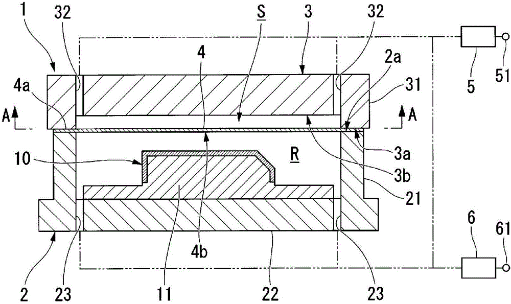
[0059] Such as figure 1 As shown, the thermoforming device 1 provided by the embodiment of the present invention is used for overmolding the adhesive sheet 4 on the substrate 10 .

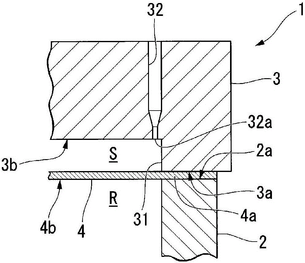
[0060] The thermoforming device 1 has a lower frame 2 having a space (accommodating area R) capable of accommodating a substrate 10 and a hot plate 3 having a frame upper edge portion 2a capable of abutting against the lower frame 2 . The abutment surface 3a. The structure is such that a resin sheet 4 is provided between the lower frame 2 and the hot plate 3 , and the sheet 4 is heated to adhere to the base material 10 for thermoforming. Here, the substrate 10 is formed into a thermoformed product by bonding the sheets 4 , and is clamped by the substrate holder 11 in the thermoforming apparatus 1 .

[0061] However, the thermoforming a...


PUM


Abstract

A thermoforming apparatus provided with: a casing material having a region for accommodating a substrate that is to be thermoformed, and a casing edge; and a heating plate, which has a heating surface that is square in planar view and a frame part that protrudes toward the casing material from the peripheral edge of the heating surface, and in which the frame part is capable of abutting against the casing edge of the casing material. The heating plate is provided with vacuum holes that open at the corner formed by the heating surface and the frame part at the periphery of the heating plate in planar view. Before adhesion, on the heating surface, of a sheet that is disposed between the casing edge of the casing material and the peripheral edge of the heating plate, there is a gap between at least a portion of the sheet and the heating surface.

Description

technical field [0001] The invention relates to a thermoforming device for thermoforming a thin sheet to shape a mold or bond it to a base material. Background technique [0002] Conventionally, a vacuum press lamination type thermoforming apparatus is known as an apparatus for adhering a sheet to the outer surface of a molding substrate (for example, refer to Patent Document 1). [0003] Among them, the conventional thermoforming device described in Patent Document 1 is configured to have upper and lower chambers, and the lower chamber accommodates the molding base material and can be equipped with a sheet on the peripheral portion of one side of the upper chamber, and the upper chamber contains Hot plate with heater. The upper chamber is connected with a vacuum tank and a pressurized tank, which can evacuate and pressurize the chamber, and the lower chamber is connected with a vacuum tank, which can evacuate the chamber. [0004] Regarding the molding method using such a...

Claims


Application Information

Patent Timeline
IPC IPC(8): B29C51/12B29C51/42
CPCB29C33/56B29C51/06B29C51/16B29C51/40B29C51/421B29C2791/006B29K2995/0074B29C37/0025B29C51/12B29C51/42B29C51/10B29C51/428
Inventor 沟口宪一寺本一典
Owner ASANO LABORATORIES CO LTD
Why Eureka
Try Eureka