
A kind of pcb circuit board cooling device and chassis

A technology of PCB circuit board and heat dissipation device, which is applied in the direction of printed circuit components, cooling/ventilation/heating transformation, etc., can solve the problems of uneven heat dissipation, slow heat dissipation, slow heat dissipation, etc. Well-designed effects

Active Publication Date: 2019-09-06
成都芯通软件有限公司
View PDF7 Cites 0 Cited by
  • Summary
  • Abstract
  • Description
  • Claims
  • Application Information

AI Technical Summary

Problems solved by technology

[0008] The purpose of the present invention is to provide a PCB circuit board heat dissipation device and a chassis for the heat dissipation method of the PCB circuit board in the prior art, which is mainly natural heat dissipation, which has the problems of slow heat dissipation and uneven heat dissipation. The board cooling device changes the heat dissipation mode of the circuit board through direct contact with the PCB circuit board, so that the heat dissipation of the PCB circuit board is faster and more uniform, which solves the problem of slow heat dissipation in the prior art relying on natural heat dissipation, and makes the various parts of the PCB circuit board The functional units give full play to their respective performances, so that the PCB circuit board has excellent performance, safe and efficient operation

Method used


Image

  • A kind of pcb circuit board cooling device and chassis
  • A kind of pcb circuit board cooling device and chassis
  • A kind of pcb circuit board cooling device and chassis

Examples


Embodiment 1

[0045] This embodiment is applied to a PCB circuit board.

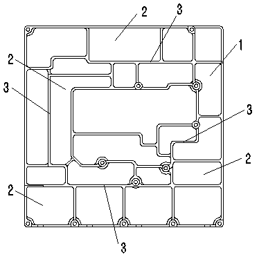
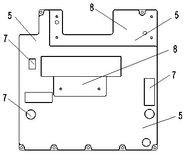
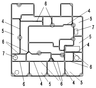
[0046] Such as Figure 1-Figure 7 As shown, the PCB circuit board heat dissipation device is used to be installed on the PCB circuit board 1, and includes a heat conduction part for contacting the heat conduction layer 3 on the PCB circuit board 1, and the heat conduction part is away from the heat conduction layer 3 One side of the heat conduction layer 3 extends, and the extended end of the heat conduction portion is connected with a heat dissipation portion.

[0047] In the prior art, the heat dissipation method of the PCB circuit board mainly adopts the natural heat dissipation method. During the use process, the PCB circuit board is installed in the chassis, and the purpose of heat dissipation is achieved through heat exchange with the air, but this natural heat dissipation The method has the characteristics of slow heat dissipation and uneven heat dissipation, which leads to an increase in the heat of the circu...

Embodiment 2

[0064] This embodiment is used for the occasion of installing a circuit board in a case.

[0065] PCB circuit board case, the PCB circuit board heat dissipation device as introduced in embodiment 1 is installed in this PCB circuit board case, during use, described PCB circuit board heat dissipation device is installed on the PCB circuit board, and heat conduction with the PCB circuit board layer contact.

[0066] Adopt above-mentioned method, arrange PCB circuit board cooling device in the case of PCB circuit board, change the structure of traditional PCB circuit board case, make the temperature of the PCB circuit board arranged in the case greatly reduce, solve the problem of PCB circuit board in the prior art. The problem of excessive temperature caused by the natural heat dissipation of the board makes the structural design of the chassis more reasonable and scientific. By arranging the heat dissipation device, the circuit board, the functional modules on the circuit board ...


PUM


Abstract

The invention relates to the technical field of network information devices, in particular to a PCB (printed circuit board) case cooling device and a case. The cooling device is used for mounting on a PCB and comprises heat conduction portions for contacting with heat conduction layers on the PCB, each heat conduction portion extends to one side far away from the corresponding heat conduction layer from the heat conduction layer to form a heat conduction rib, plate-shaped cooling portions are connected at the extending tail ends of the heat conduction portions, the cooling device directly contacts with the PCB, a natural cooling mode of the PCB is changed, the cooling device is rapider and more uniform in cooling by the aid of a heat conduction device and solves the problems of slow cooling of a natural cooling mode in the prior art, so that the PCB is excellent in performance and safe and efficient to run, all heat conduction ribs and cooling boards are connected into an integral frame structure, each functional unit on the PCB is enclosed a mutual isolated closed space, so that signals in the case cannot be mutually interfered, and the cooling device has better electromagnetic shielding effects on each functional unit and the whole printed circuit board.

Description

technical field [0001] The invention relates to the technical field of network information equipment, in particular to a PCB circuit board chassis cooling device and the chassis. Background technique [0002] PCB (Printed Circuit Board), the Chinese name is printed circuit board, also known as printed circuit board, is an important electronic component, a support for electronic components, and a carrier for electrical connections of electronic components. Such as figure 1 As shown, the PCB circuit board 1 includes a plurality of unit cells 2, and each unit cell 2 is arranged with more electronic components, and a heat conduction layer 3 is arranged between the unit cells 2, and the heat conduction layer 3 is a thin metal strip. The heat conduction layer 3 is arranged around each unit cell, and divides the PCB circuit board 1 into multiple independent areas, so that each unit cell 2 appears to have a clear boundary. [0003] Since there are many electronic components arrang...

Claims


Application Information

Patent Timeline
Patent Type & Authority Patents(China)
IPC IPC(8): H05K7/20H05K1/02
Inventor 黄显杰肖相余
Owner 成都芯通软件有限公司
Learn More