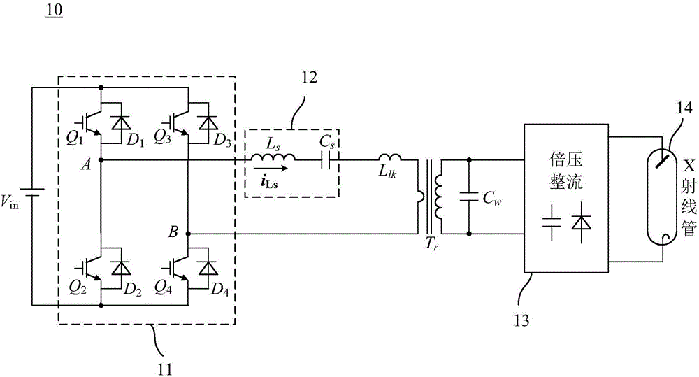
X-ray high-voltage generator and circuit and method for controlling series resonant converter
A series resonance, control circuit technology, applied in X-ray equipment, control/regulation systems, high-efficiency power electronic conversion, etc., to maintain adaptability, reduce possibilities, and reduce turn-on losses
- Summary
- Abstract
- Description
- Claims
- Application Information
AI Technical Summary
Problems solved by technology
Method used
Image
Examples
no. 1 example
[0041] According to this embodiment, the leading bridge arm of the inverter circuit 51 adopts bipolar modulation, and the opening of the lagging bridge arm is the same as that of the leading bridge arm, and the shutdown signal is obtained by detecting the zero signal of the series resonant circuit current Achieved. Figure 6 is a modulation waveform diagram of the series resonant inverter according to the first embodiment of the present invention. refer to Figure 6 As shown, the first drive signal S1 and the second drive signal S2 constitute bipolar modulation; the third drive signal S3 drives the conduction moment of the third switching device Q3 and the second drive signal S2 drives the conduction of the second switch device Q2 The time is the same, the turn-on time of the fourth driving signal S4 driving the fourth switching device Q4 is the same as the turning-on time of the first driving signal S1 driving the first switching device Q1 . In addition, the turn-off time o...
no. 2 example
[0054] According to this embodiment, the switching devices Q1 and Q3 of the inverter circuit 51 adopt bipolar modulation, the switching device Q2 and the switching device Q3 have the same conduction time, the switching device Q4 and the switching device Q1 have the same conduction time, and the second switch The turn-off signal of the device Q2 and the fourth switching device Q4 is realized by detecting the zero signal of the resonant cavity current of the series resonant converter. Figure 8 is a modulation waveform diagram of the series resonant converter according to the second embodiment of the present invention. refer to Figure 8 As shown, the first driving signal S1 and the third driving signal S3 constitute bipolar modulation; the second driving signal S2 drives the conduction moment of the second switching device Q2 and the third driving signal S3 drives the third switching device Q3 to conduct The time is the same, the turn-on time of the fourth driving signal S4 dr...
PUM
 Abstract
Description
Claims
Application Information
 - R&D
- Intellectual Property
- Life Sciences
- Materials
- Tech Scout
- Unparalleled Data Quality
- Higher Quality Content
- 60% Fewer Hallucinations
Browse by: Latest US Patents, China's latest patents, Technical Efficacy Thesaurus, Application Domain, Technology Topic, Popular Technical Reports.
© 2025 PatSnap. All rights reserved.Legal|Privacy policy|Modern Slavery Act Transparency Statement|Sitemap|About US| Contact US: help@patsnap.com


