
Novel clamping connection type photovoltaic conjunction box

A voltage junction box and snap-on technology, applied in the field of new snap-on photovoltaic junction boxes, can solve the problems of inconvenient operation of welding busbars, poor sealing of wiring holes, and impact on appearance, and achieve suitable mass production. , to avoid the fixed method, the effect of stable and convenient installation

Inactive Publication Date: 2017-02-22
JIANGSU HAITIAN MICROELECTRONICS TECH
View PDF6 Cites 2 Cited by
  • Summary
  • Abstract
  • Description
  • Claims
  • Application Information

AI Technical Summary

Problems solved by technology

[0003] The junction box in the prior art is mainly composed of three parts: the box body, cables and metal connectors, which are glued together with the back plate of the module through silica gel, and the outgoing lines in the module are connected together through the internal lines in the junction box. The lines are connected with the external cables to make the components conduct with the external cables. There are diodes in the junction box to ensure that the components can work normally when the light is blocked. Most of the bus strips are fixed by soldering. The disadvantages of this assembly method are that it is inconvenient to operate when welding the confluence belt, and it affects the appearance, it is difficult to overhaul, and the sealing of the wiring holes is not good, the amount of glue injected is large, and it is difficult to remove the wires

Method used


Image

  • Novel clamping connection type photovoltaic conjunction box
  • Novel clamping connection type photovoltaic conjunction box
  • Novel clamping connection type photovoltaic conjunction box

Examples


Embodiment Construction

[0026] The specific embodiments of the present invention will be further described below in conjunction with the accompanying drawings.

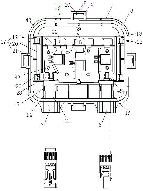
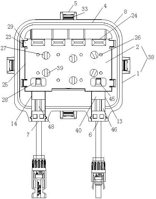
[0027] A new clip-on photovoltaic junction box, including a box body, metal parts and pressing blocks, wherein the box body includes a box frame, a box bottom, a box cover and a sealing ring, and a number of first clips are arranged on the edge of the box frame. Blocks, wiring positive outlets and wiring negative outlets, the four corners of the outer wall and the inner wall of the box frame are provided with rounded corners, the number of the first clamping blocks is 4, and they are distributed symmetrically around the box frame, and the first The cross-section of the block is L-shaped, and a first bayonet is provided inside, and a first buckle is provided on one side of the first bayonet. A groove is provided, and the box frame is provided with a first sealing groove, a positive wiring channel and a negative wiring channel, the first seali...


PUM


Abstract

The invention relates to a novel clamping connection type photovoltaic conjunction box. The novel clamping connection type photovoltaic conjunction box comprises a box body, a metal piece and pressure blocks, wherein the box body comprises a box frame, a box bottom, a box cover and a sealing ring, the edge of the box frame is provided with a plurality of first clamping blocks, a wiring positive outlet and a wiring negative outlet, the box frame is provided with a first sealing groove, a positive routing channel and a second routing channel, the inner wall of the box frame is provided with a first clamping connection set and a second clamping connection set, the first clamping connection set comprises two second clamping blocks, a first clamping groove and a second clamping groove, the box bottom is provided with a plurality of terminal installation grooves and a plugboard, the side wall of the box cover is provided with a plurality of second buckling blocks, the metal piece is provided with a plurality of conducting bars, the conducting bars are provided with a plurality of terminals, installation holes and fuses, and the pressure blocks are internally provided with wiring holes. According to the invention, the structure is novel, the design is reasonable, a conventional soldering fixation mode is avoided, the sealing is good, the installation is stable and convenient, the cost is decreased, and therefore, the novel clamping connection type photovoltaic conjunction box is suitable for large-scale production.

Description

technical field [0001] The invention relates to a novel snap-in photovoltaic junction box, which belongs to the technical field of electrical connectors. Background technique [0002] Photovoltaic junction box is a connector between the solar cell array composed of solar cell components and the solar charging control device. It is a cross-field comprehensive design that combines electrical design, mechanical design and material science. The junction box of solar photovoltaic modules is very important in the composition of solar modules, and its main function is to connect the power generated by solar cells with external lines. [0003] The junction box in the prior art is mainly composed of three parts: the box body, cables and metal connectors, which are glued together with the back plate of the module through silica gel, and the outgoing lines in the module are connected together through the internal lines in the junction box. The lines are connected with the external cab...

Claims


Application Information

Patent Timeline
Patent Type & Authority Applications(China)
IPC IPC(8): H02S40/34
CPCH02S40/34H02S40/345Y02E10/50
Inventor 李霖
Owner JIANGSU HAITIAN MICROELECTRONICS TECH
Learn More