Wall type electronic equipment charging apparatus
A technology of electronic equipment and charging device, which is applied to battery circuit devices, circuit devices, current collectors, etc., can solve the problems of not being able to find the charger, the influence of the data line, and the inconvenience of actual operation, etc., to achieve a simple overall structure, charging High efficiency and reducing line loss
- Summary
- Abstract
- Description
- Claims
- Application Information
AI Technical Summary
Problems solved by technology
Method used
Image
Examples
Embodiment 1
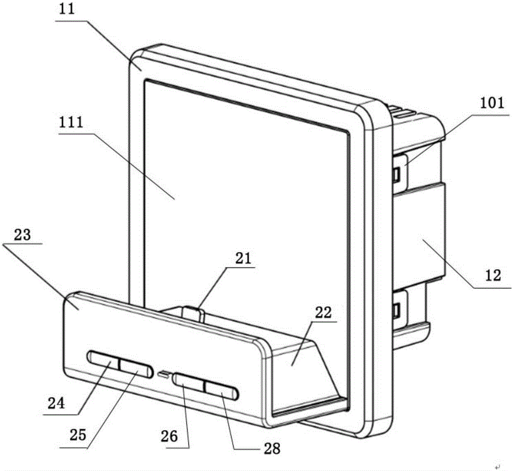
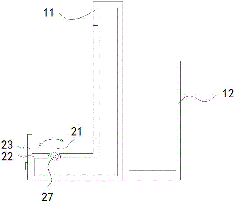
[0028] Such as Figures 1 to 2 As shown, a wall-type charging device for electronic equipment. The electronic equipment in this embodiment takes a mobile phone as an example, and includes a main casing installed on the wall and a power supply assembly arranged on the main casing. The power supply assembly includes a transformer The voltage element converts the alternating current into direct current for charging the mobile phone. The main housing is provided with an electrical output terminal for charging the mobile phone. The electrical output terminal is connected to the power supply assembly. The main housing is provided with There is a bracket for placing a mobile phone, and the bracket is provided with the electrical output end; the electrical output end includes a charging connector 21 that matches the charging interface of the mobile phone. With this embodiment, the user does not need to plug in additional data lines, Directly plug the charging interface of the mobile p...
Embodiment 2
[0040]The difference between this embodiment and Embodiment 1 is that the bracket and the front panel are not integral structures. The bracket in this embodiment is movable, specifically, it can slide in the front and rear directions. The chute can be extended to the rear shell to strengthen the length of the chute. The bracket is slidably installed in the chute, and the front panel is provided with an avoidance gap for avoiding the charging connector, so that the charging connector When the shelf slides, it will not hit the front panel. When the user needs to charge, slide the bracket out of the chute, and when not charging, slide the bracket into the chute, so as to prevent the user from touching the bracket sometimes.
Embodiment 3
[0042] The difference from Embodiment 1 is that in this embodiment, the charging connector includes two connectors, namely a MicroUSB connector and a Lightning connector, both of which are provided on the support body. Control the fast charging button and slow charging button of these two connectors respectively, that is, there are two fast charging buttons and two slow charging buttons, and there are also two sets of first charging circuit and second charging circuit, each group of fast charging button and slow charging The charging button is correspondingly connected to one of the first charging circuit and the second charging circuit.
PUM
 Abstract
Description
Claims
Application Information
 - R&D
- Intellectual Property
- Life Sciences
- Materials
- Tech Scout
- Unparalleled Data Quality
- Higher Quality Content
- 60% Fewer Hallucinations
Browse by: Latest US Patents, China's latest patents, Technical Efficacy Thesaurus, Application Domain, Technology Topic, Popular Technical Reports.
© 2025 PatSnap. All rights reserved.Legal|Privacy policy|Modern Slavery Act Transparency Statement|Sitemap|About US| Contact US: help@patsnap.com


