
Inspection system and inspection method of valve hall robot based on video monitoring linkage system

A linkage system and video monitoring technology, applied in the field of intelligent power transmission and transformation, can solve problems such as inability to identify abnormalities independently, limited monitoring range, and inconvenient geographical location of power transformation equipment

Active Publication Date: 2017-02-22
STATE GRID CORP OF CHINA +1
View PDF10 Cites 27 Cited by
  • Summary
  • Abstract
  • Description
  • Claims
  • Application Information

AI Technical Summary

Problems solved by technology

[0020] The purpose of the present invention is to overcome the defects of the existing technology, and provide a valve hall robot inspection system and inspection method based on the video monitoring linkage system. Through the coordination and cooperation of the robot inspection and fixed-point cameras, it solves the problem of limited monitoring range, variable The geographical location of electrical equipment is not convenient for arranging monitoring points; solve the problem of inability to independently identify abnormalities and intelligent linkage security, fire protection and online equipment management systems; use visible light video and infrared thermal imaging cameras to monitor fires in a mixed way to reduce fire false alarms

Method used


Image

  • Inspection system and inspection method of valve hall robot based on video monitoring linkage system
  • Inspection system and inspection method of valve hall robot based on video monitoring linkage system
  • Inspection system and inspection method of valve hall robot based on video monitoring linkage system

Examples


Embodiment Construction

[0126] The present invention will be described in further detail below in conjunction with the accompanying drawings and specific embodiments, but not as a limitation of the present invention.

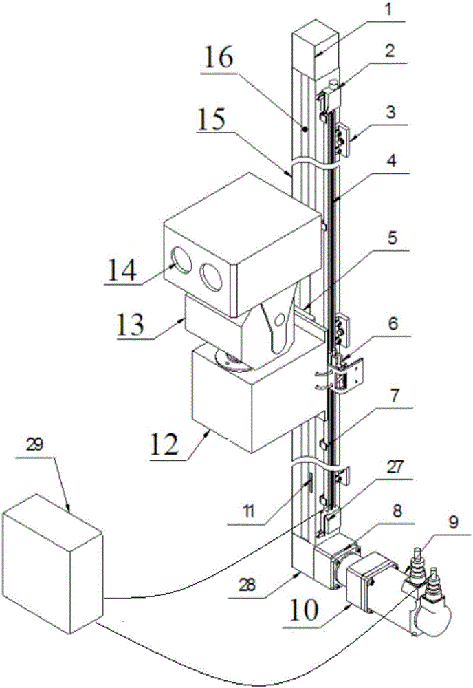
[0127] Such as figure 1 As shown, the intelligent inspection robot system for the valve hall of the converter station based on the video monitoring linkage system mainly includes a linkage analysis control host 101, a data storage server 102, a communication server 103 interacting with external systems, an inspection robot 104, and a linkage analysis robot. The wireless communication module 105 and the auxiliary fixed point monitoring subsystem 106 for controlling the communication between the host computer and the inspection robot,

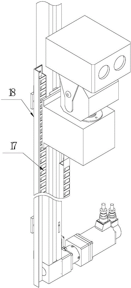
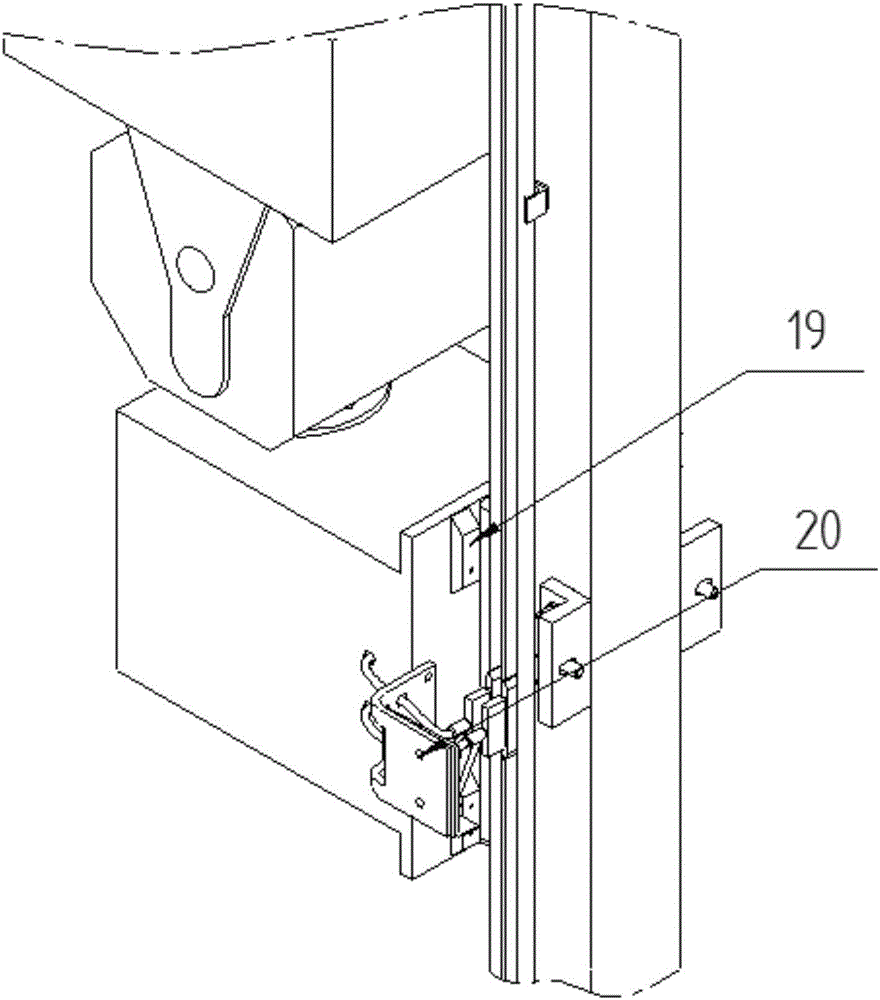
[0128] The inspection robot includes a robot terminal system 42, which communicates with the remote control system 41. The robot terminal system 42 includes a profile rail 15, which is vertically installed on the wall of the valve hall. A motion mechanis...


PUM


Abstract

The invention provides an inspection system and an inspection method of a valve hall robot based on a video monitoring linkage system. The inspection system comprises a linkage analysis control host, a communication server and an auxiliary fixed point monitoring subsystem; an inspection robot comprises a robot terminal system; the robot terminal system comprised a track; a moving mechanism, a motion driving mechanism and a detection mechanism are arranged on the track; the inspection system and the inspection method have the advantage that real-time unmanned detection requirement of valve hall equipment is met; by coordinating inspection of the robot with a fixed point camera, the problems that the monitoring range is limited and the geographic position of substation equipment is not convenient for arrangement of monitoring points are solved; the problems that the abnormality cannot be autonomously identified as well as intelligent linkage security and protection, firefighting and online equipment management system are solved; fires are monitored by using a mixing mode of a visible light video and a thermal infrared imager, so the fires can be reduced; according to the inspection system and the inspection method provided by the invention, by adopting double detection of the visible light video and an infrared thermal video, the false alarm rate of fire alarms is reduced, and the processing efficiency of the fire alarms is improved.

Description

[0001] 【Technical field】 [0002] The invention belongs to the field of intelligent power transmission and transformation, and relates to a valve hall robot inspection system and inspection method based on a video monitoring linkage system. [0003] 【Background technique】 [0004] The valve hall is an important part of the converter station, and it is very important to ensure the normal operation of the equipment in the valve hall. On the one hand, the valve hall equipment such as the valve tower needs to have sufficient reliability, on the other hand, it also needs to be detected in time to find and repair potential hidden dangers and ensure the normal operation of the converter station system. Real-time detection of valve hall equipment is of great significance to ensure its reliable and safe operation. The use of orbital robots can conveniently and flexibly detect the equipment in the valve hall in real time and understand the operating status of the equipment. [0005] Th...

Claims


Application Information

Patent Timeline
IPC IPC(8): G05B19/048
CPCG05B19/048
Inventor 张辉苏煜白桢李小刚李小军马新宇王瑜娟韦征李红霞刘红苗魏庆
Owner STATE GRID CORP OF CHINA
Learn More