Optical fiber connector and assembling method thereof

An optical fiber connector and assembly method technology, applied in the directions of light guides, optics, instruments, etc., can solve the problems that cannot be solved by pressing and regrinding, the ceramic end face and core wire are damaged, the ferrule ceramic surface is damaged, etc., and the structure is simple. , Solve the effect of unmanufacturable and low cost

Active Publication Date: 2017-02-22
SEIKOH GIKEN HANGZHOU
View PDF8 Cites 0 Cited by
  • Summary
  • Abstract
  • Description
  • Claims
  • Application Information

AI Technical Summary

Problems solved by technology

[0005] The use of glue has the following problems: when the metal sleeve is in use, it will be laser welded to other devices, and the high temperature at the moment of laser welding can directly evaporate the glue; during the assembly process of the product, the ceramic surface of the ferrule will be damaged, affecting The performance of the product; the use of the product under extreme conditions may cause the glue to fail
The use of forced mechanical press-fitting has the following problems: ceramic end faces and core wires are damaged, which affects product performance
[0006] To ensure the optical parameters and performance of the PC end of the optical fiber connector, the conventional press-in regrinding method has been unable to solve the problem

Method used


Image

  • Optical fiber connector and assembling method thereof
  • Optical fiber connector and assembling method thereof
  • Optical fiber connector and assembling method thereof

Examples


Embodiment Construction

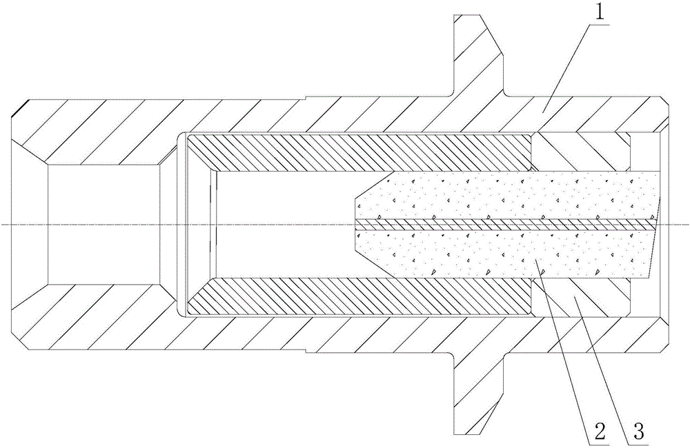
[0019] Such as figure 1 As shown, the optical fiber connector includes a metal sleeve 1 and a ceramic ferrule 2, a metal ring 3 is provided between the metal sleeve and the ceramic ferrule, and the metal ring is sleeved on the ceramic ferrule And located in the middle of the ceramic ferrule. The metal ring tightly fits with the ceramic ferrule. The end face of the ceramic ferrule is located inside the end face of the metal sleeve to protect the end face of the ceramic ferrule from damage.

[0020] The assembly method of the optical fiber connector described above includes step 1: grinding the end face of the ceramic ferrule, and pressing the ceramic ferrule into the metal ring; step 2: pressing the ground ceramic ferrule into the metal sleeve.

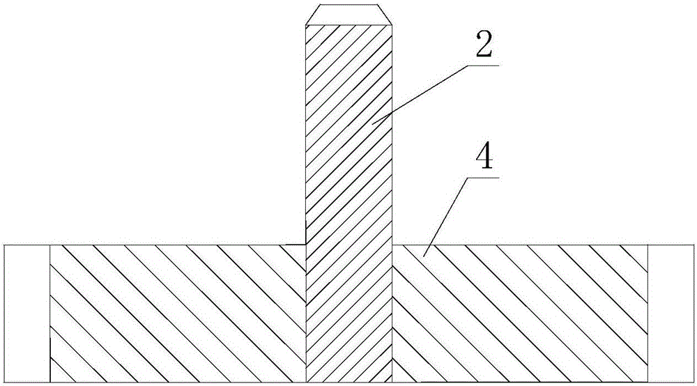
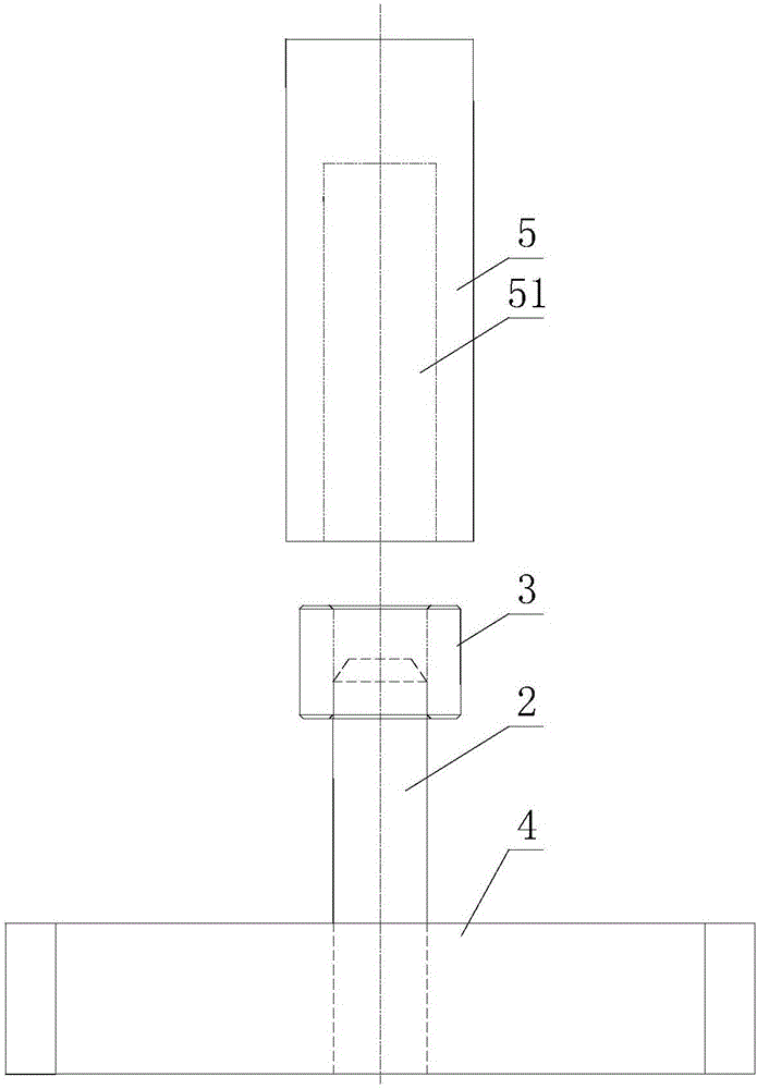
[0021] The first step includes the following steps: (1) grinding the end face of the ceramic ferrule; (2) embedding the ground ceramic ferrule into the bottom plate I4 (such as figure 2 shown); (3) Buckle the metal ring on the grou...


PUM


Abstract

The invention discloses an optical fiber connector which comprises a metal sleeve and a ceramic insertion core. A metal ring is arranged between the metal sleeve and the ceramic insertion core. The metal ring sleeves the ceramic insertion core and is arranged at the middle part of the ceramic insertion core. According to the optical fiber connector and the assembling method, through performing differentiated adjustment on the structure and using the transition metal ring, a mechanical matching force is used for fixing each assembly. In the assembling process, the end surfaces of the ceramic insertion core and the core wire are effectively protected from damage. Through the assembling method, similar products can be produced and furthermore high product performance and mechanical requirements can be satisfied. The optical fiber connector and the assembling method thereof have advantages of simple structure, relatively high efficiency, low cost, mass production of products, relatively low requirement for production process, and effective settlement of a problem of incapability of producing individual structures.

Description

technical field [0001] The invention relates to an optical fiber connector and an assembly method thereof. Background technique [0002] TOSA (Optical Transmitting Sub-module), ROSA (Optical Receiving Sub-module) and other Receptacle structures, as the most important devices in optical communication devices, with the development of technology, their structures are becoming more and more complex. Many structures used to be The methods are difficult to solve: due to its performance requirements, it is an important issue to protect the ceramic ferrule (Ferrule) and realize simple and convenient assembly. [0003] In optical communication products, the ceramic ferrule is matched with the metal sleeve, and the performance of the two end faces of the ground ceramic ferrule must be guaranteed. The assembly and grinding of the ceramic ferrule directly affect the communication performance. It is particularly important to effectively control the force of the ceramic ferrule and effec...

Claims


Application Information

Patent Timeline
Patent Type & Authority Applications(China)
IPC IPC(8): G02B6/38
CPCG02B6/3825G02B6/3863
Inventor 李欣欣李秋平何彩莉
Owner SEIKOH GIKEN HANGZHOU
Why Eureka
Try Eureka