
A device for real-time imaging using spatially chirped terahertz pulses

A terahertz pulse and real-time imaging technology, which is applied to measuring devices, instruments, scientific instruments, etc., can solve the time-consuming problems and achieve the effect of real-time fast imaging

Inactive Publication Date: 2018-01-16
UNIV OF SHANGHAI FOR SCI & TECH
View PDF4 Cites 0 Cited by
  • Summary
  • Abstract
  • Description
  • Claims
  • Application Information

AI Technical Summary

Problems solved by technology

[0005] In order to solve a series of problems caused by spatial two-dimensional scanning, the present invention proposes a real-time imaging device using terahertz pulses with spatial chirp characteristics. The chirped terahertz pulse is used to image the measured object. The frequency information of the terahertz pulse is used to represent the coordinate information of different positions of the measured object, and the change of the terahertz frequency amplitude is used to represent the shape characteristics of the object. Fast imaging can be achieved by performing two-dimensional scanning, which overcomes the time-consuming problem of the existing technology because of the need for two-dimensional scanning

Method used


Image

  • A device for real-time imaging using spatially chirped terahertz pulses
  • A device for real-time imaging using spatially chirped terahertz pulses
  • A device for real-time imaging using spatially chirped terahertz pulses

Examples


Embodiment Construction

[0039] In order to make the technical means, creative features, goals and effects achieved by the present invention easy to understand, the following embodiments describe in detail the principle, structure and usage of the device for real-time imaging using spatially chirped terahertz pulses of the present invention in conjunction with the accompanying drawings elaborate.

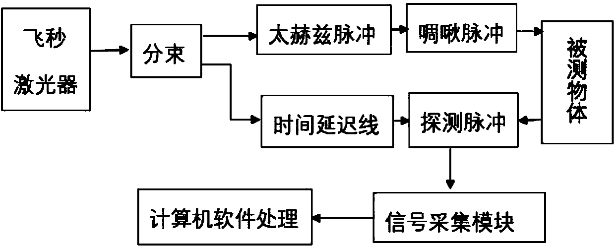
[0040] figure 1 Schematic diagram of the principle of the device for real-time imaging using spatially chirped terahertz pulses of the present invention.

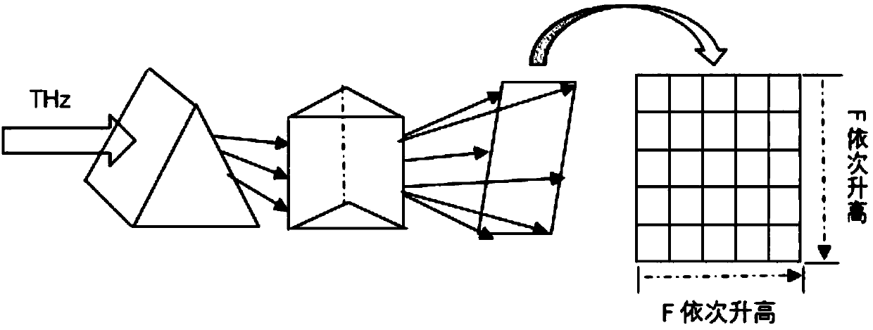
[0041] figure 2 Schematic diagram of the basic principle for forming chirped terahertz pulses.

[0042] Such as figure 1 As shown, the laser pulse output by the femtosecond laser on the left is divided into two beams by the beam splitter, and one beam is used as pump light to generate terahertz pulses. The generated terahertz pulses first pass through a silicon prism placed horizontally, so that Its frequency expands linearly in the vertical space, ...


PUM


Abstract

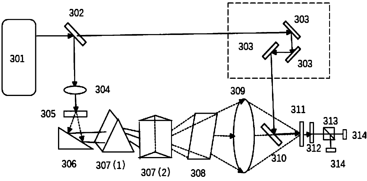
A device for performing real-time imaging by means of a spatial chirped terahertz pulse is used for realizing terahertz real-time imaging of an object. The device comprises the components of a laser; a light splitting device which is used for splitting laser that is generated by a laser device into a first beam and a second beam; a pulse optical path unit which receives the first beam and comprises a semiconductor antenna, a pair of silicon prisms which are arranged in a non-overlapped manner, an imaging lens, and electro-optical crystal which is used for receiving light that penetrates through the imaging lens, wherein the semiconductor antenna, the pair of silicon prisms, the imaging lens and the electro-optical crystal are successively arranged in an optical path; a detecting optical path unit which receives the second beam and comprises a high-reflectivity lens set and a reflector member, wherein the high-reflectivity lens set and the reflector member are successively arranged in the optical path and are used for time delay, wherein the reflector member is arranged between the imaging lens and the electro-optical crystal and is used for combining the reflected light and the light that penetrates through the imaging lens and illuminating the combined light to the electro-optical crystal; and a signal acquiring and processing unit which is connected with the electro-optical crystal and acquires the signal on the electro-optical crystal and performs processing for obtaining a terahertz image of the object, wherein the object is placed between the silicon prisms and the imaging lens.

Description

technical field [0001] This patent relates to an optical device for real-time imaging with terahertz pulses, especially a device for fast imaging of objects using terahertz pulses with spatial chirp characteristics, which belongs to the field of optoelectronics. Background technique [0002] Terahertz radiation can penetrate most non-polar dielectrics, and the photon energy of terahertz radiation is only millielectron volts, which is less than the bond energy of most chemical bonds, and it will not cause harmful ionization reactions when interacting with objects, so it is very It is suitable for carrier imaging and perspective imaging of opaque objects. [0003] The most basic terahertz wave imaging method is the Roster scanning method, which uses the focusing element to focus the terahertz wave on a point in space, places the object under test at the focal point, and scans the object under test in a plane perpendicular to the transmission direction of the terahertz wave. C...

Claims


Application Information

Patent Timeline
Patent Type & Authority Patents(China)
IPC IPC(8): G01J3/28
CPCG01J3/2823
Inventor 马超李敏张玲曾和平
Owner UNIV OF SHANGHAI FOR SCI & TECH
Learn More