Air duct with total heat exchanging function

A heat exchange tube and full heat exchange technology, which is applied in the field of air ducts with full heat exchange function, can solve problems such as air mixing and affect the quality of fresh air, and achieve the effect of reducing ventilation resistance and ensuring the quality of fresh air

Inactive Publication Date: 2017-02-22
爱康森德(深圳)空气技术有限公司
View PDF5 Cites 1 Cited by
  • Summary
  • Abstract
  • Description
  • Claims
  • Application Information

AI Technical Summary

Problems solved by technology

[0003] Aiming at the deficiencies of the prior art, the present invention proposes an air duct with a full heat exchange function. A separate tube is provided at both ends of the heat exchange tube, aiming at solving the problem of the existing heat exchangeable air duct due to the heat exchange tube The outdoor air ducts and indoor air ducts are too close to each other, which may cause air mixing and affect the quality of fresh air

Method used


Image

  • Air duct with total heat exchanging function
  • Air duct with total heat exchanging function
  • Air duct with total heat exchanging function

Examples


Embodiment 1

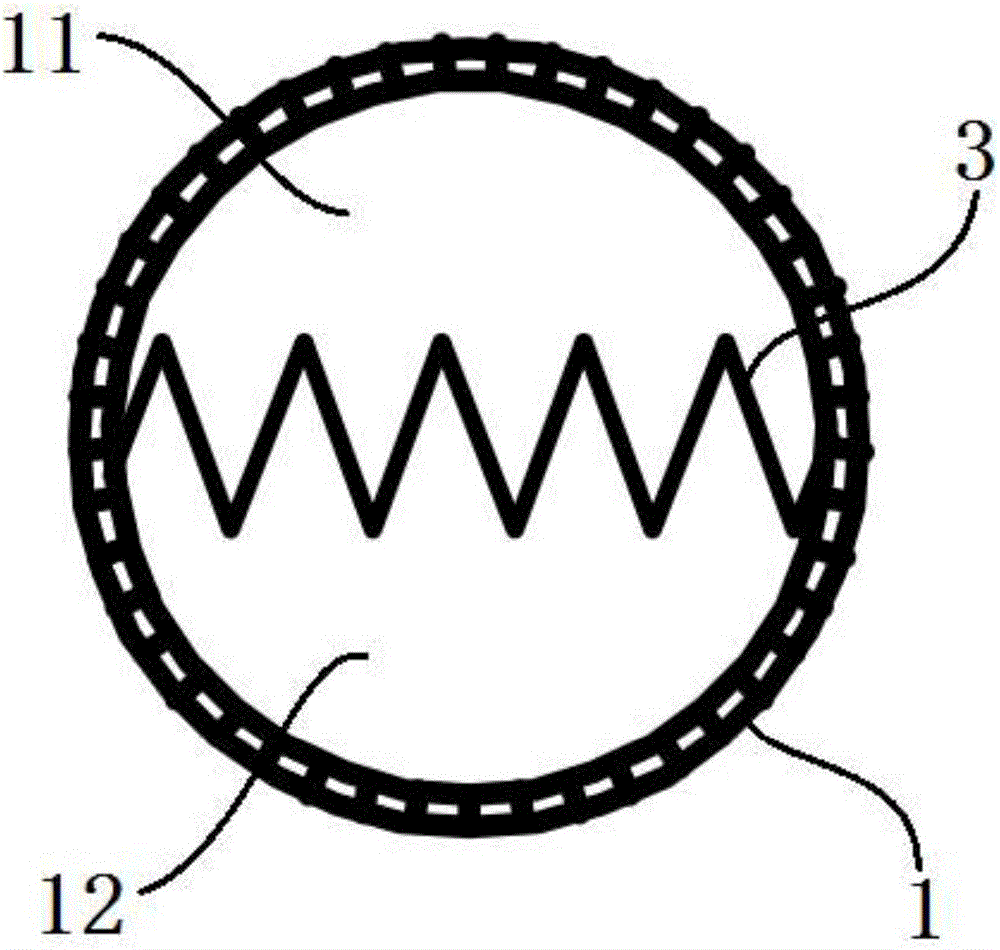
[0036] Such as figure 2 As shown, the thermally conductive spacer 3 is in the shape of a flat plate. The heat-conducting insulating layer 3 is arranged in the heat-exchange tube 1 along the diameter direction of the heat-exchange tube 1 , thereby dividing the heat-exchange tube 1 into a first heat-exchange channel 11 and a second heat-exchange channel 12 . The first manifold 21 and the second manifold 22 of the separation pipe 2 are plane-symmetric with respect to the flat heat-conducting insulating layer 3 . The cross-section of the heat-conducting insulating layer 3 is wavy, specifically, it may be in a saw-tooth shape, a wave shape, or a truncated cone shape, so as to increase heat exchange efficiency.

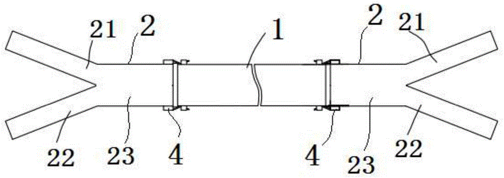
[0037] The heat exchange tube 1 and the two separating tubes 2 can be integrally formed. In addition, if figure 1 As shown, the heat exchange tube 1 can also be plugged with the two separation tubes 2 respectively. Specifically, the separation pipe 2 also includes a tr...

Embodiment 2

[0044] Such as Figure 5As shown, the thermally conductive spacer 3 is cylindrical. The cross-section of the heat-conducting interlayer 3 is circular, and may also be square or elliptical. The heat conduction interlayer 3 is sleeved in the heat exchange tube 1 , and the heat conduction interlayer 3 is coaxial with the heat exchange tube 1 . Several supporting ribs 101 are erected on the inner wall of the heat exchange tube 1 , and the supporting ribs 101 are used to support the heat-conducting insulating layer 3 . Each support rib 101 is distributed at equal intervals around the heat conduction spacer 3 around the tube axis of the heat exchange tube 1 , so that the position of the heat conduction spacer 3 is fixed. The inner cavity of the heat conducting insulating layer 3 is the first heat exchange channel 11 ; the annular channel between the heat conducting insulating layer 3 and the heat exchanging tube 1 forms the second heat exchanging channel 12 . The cross-section of...


PUM


Abstract

The invention discloses an air duct with total heat exchanging function. The air duct with the total heat exchanging function comprises a heat exchanging pipe, and two separating pipes which are correspondingly positioned at two ends of the heat exchanging pipe, wherein a heat conducting interlayer is arranged in the heat exchanging pipe and extends in the same direction with the heat exchanging pipe; the heat exchanging pipe is divided by the heat conducting interlayer into a first heat exchanging channel and a second heat exchanging channel which is adjacent to the first heat exchanging channel; each separating pipe comprises a first branch pipe and a second branch pipe; an angle is formed between the first branch pipe and the second branch pipe; the first branch pipe communicates with the first heat exchanging channel; the second branch pipe communicates with the second heat exchanging channel. According to the air duct with the total heat exchanging function, the separating pipes are correspondingly connected to the two ends of the heat exchanging pipe; ports of the first branch pipe and the second branch pipe of each separating pipe are separated, so that outdoor air and indoor air cannot be mixed while entering or exiting the heat exchanging pipe, and thus the fresh air quality can be ensured.

Description

technical field [0001] The invention relates to the technical field of air conditioning and air purification, in particular to an air duct with full heat exchange function. Background technique [0002] The air quality treatment system meets people's requirements for temperature, humidity, cleanliness and wind speed comfort. However, when the existing heat-exchanging air ducts in the air quality treatment system are in use, because the nozzles of the outdoor air duct and the indoor air duct are too close, it is easy to cause air mixing and affect the quality of fresh air. Contents of the invention [0003] Aiming at the deficiencies of the prior art, the present invention proposes an air duct with a full heat exchange function. A separate tube is provided at both ends of the heat exchange tube, aiming at solving the problem of the existing heat exchangeable air duct due to the heat exchange tube Because the outdoor air ducts and indoor air ducts are too close to each othe...

Claims


Application Information

Patent Timeline
Patent Type & Authority Applications(China)
IPC IPC(8): F24F7/04F24F13/02F24F12/00F24F13/30
CPCF24F7/04F24F12/001F24F13/02F24F13/30
Inventor 李锡蔺勇智潘志升李春海朱云亮
Owner 爱康森德(深圳)空气技术有限公司
Why Eureka
Try Eureka