Combined boiler smoke waste heat recycling system

A waste heat recovery system, boiler flue gas technology, applied in preheating, feed water heaters, lighting and heating equipment, etc., can solve the problems of high flue gas waste heat temperature, high gas content, low heat utilization rate, etc., and achieve desulfurization efficiency High, improve boiler efficiency, and reduce the amount of evaporated water

Active Publication Date: 2017-02-22
江苏海德节能科技有限公司
View PDF6 Cites 0 Cited by
  • Summary
  • Abstract
  • Description
  • Claims
  • Application Information

AI Technical Summary

Problems solved by technology

In the use of current industrial boilers, there are generally problems such as low heat utilization rate, high temperature of waste heat in exhaust flue gas, and high content of polluting environmental gases in flue gas.

Method used


Image

  • Combined boiler smoke waste heat recycling system

Examples


Embodiment Construction

[0009] The present invention will be further described below in conjunction with the accompanying drawings and embodiments.

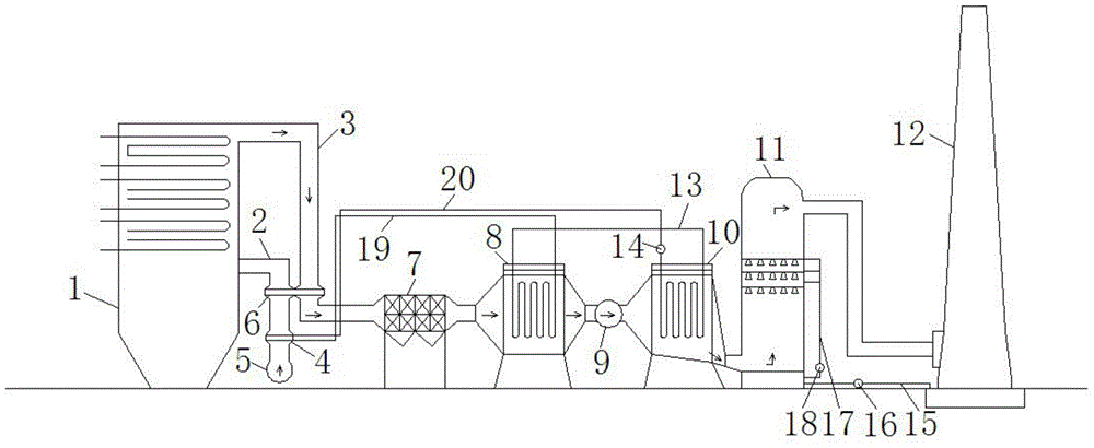
[0010] Such as figure 1 As shown, a combined boiler flue gas waste heat recovery system according to the present invention includes a boiler 1, an air duct 2 is provided at the middle and upper part outside the furnace wall of the boiler 1, and an air duct 2 is provided at the upper part outside the furnace wall of the boiler 1. There is a flue 3, an air heater 4 is provided on the air duct 2, a blower 5 is provided below the air heater 4, and an air blower 5 is arranged on the air duct 2 and the flue 3 above the air heater 4. There is an air preheater 6, the outlet of the flue 3 is connected to one side of the electrostatic precipitator 7, and the other side of the electrostatic precipitator 7 is connected to the side of the first flue gas cooler 8, and the first flue gas The other side of the cooler 8 is connected to one side of the booster fan 9, th...


PUM


Abstract

The invention relates to a combined boiler smoke waste heat recycling system. The combined boiler smoke waste heat recycling system comprises a boiler, an air way and a smoke way are arranged on the boiler, an air heater is arranged on the air way, a forced draught blower is arranged below the air heater, air preheaters are arranged at the positions, above the air heater, of the air way and the smoke way, an outlet of the smoke way is connected with one side of an electrostatic precipitator, the other side of the electrostatic precipitator is connected with one side of a first smoke cooler, the other side of the first smoke cooler is connected with the one side of a pressurized draught fan, and the other side of the pressurized draught fan is connected with one side of a second smoke cooler; the other side of the second smoke cooler is connected with the lower portion of one side of a desulfurizing tower, and the upper portion of the other side of the desulfurizing tower is connected with the lower portion of one side of a wet chimney. Exhaust heat is recycled, the exhaust temperature is reduced, the water consumption of the desulfurizing tower is saved, and the boiler efficiency is improved.

Description

technical field [0001] The invention relates to a waste heat recovery system, in particular to a flue gas waste heat recovery system. Background technique [0002] At present, flue gas is the main way for general energy-consuming equipment to waste energy. For example, the exhaust gas of boilers consumes about 15% of the energy. gas emissions. In the use of current industrial boilers, there are generally problems such as low heat utilization rate, excessively high temperature of exhaust gas waste heat, and excessively high content of polluting environmental gases in the flue gas. At present, industrial boilers are the main thermal power equipment in our country. With the rapid economic development in China, energy consumption is increasing day by day, and the problem of deteriorating urban air quality is becoming more and more prominent. Contents of the invention [0003] Purpose of the invention: The purpose of the invention is to overcome the deficiencies in the prior ...

Claims


Application Information

Patent Timeline
IPC IPC(8): F22D1/36F23J15/02
Inventor 舒少辛蔡天忠
Owner 江苏海德节能科技有限公司
Why Eureka
Try Eureka