Disc-shaped spring damper with rigidity capable of being preset
A kind of butterfly spring and damper technology, which is applied to building components, building types, shockproof, etc., can solve the problems of inability to stretch, consume energy and reduce vibration, shorten the effective working length of springs, etc. Effect
- Summary
- Abstract
- Description
- Claims
- Application Information
AI Technical Summary
Problems solved by technology
Method used
Image

Examples
example 1
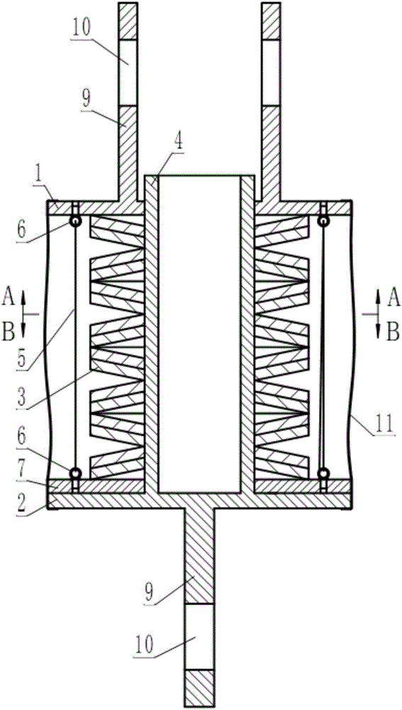
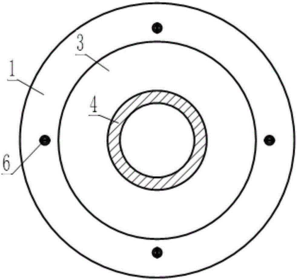
[0037] see Figure 1~3 , this example is a damper used for seismic reinforcement of building structures. The damper includes a disc-shaped upper end plate 1 and a lower end plate 2. A disc spring group 3 is arranged between the upper and lower end plates, wherein the lower end plate 2 is A guide rod 4 is provided, and the guide rod 4 passes through the upper end plate 1 upwardly along the center hole of the disc spring group 3; the disc spring group 3 is composed of sixteen disc springs stacked together.
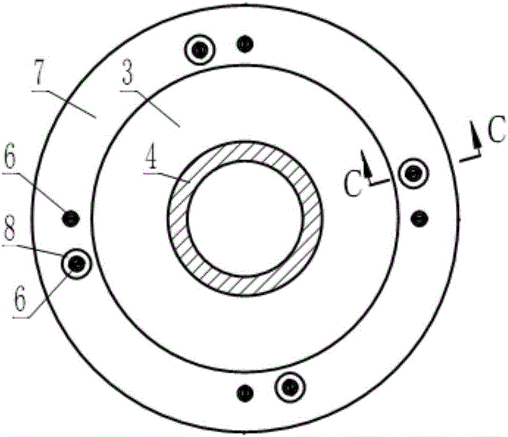
[0038] see Figure 1~4 , There is also a back pressure device between the upper and lower end plates, and the back pressure device includes four preloaded steel wire ropes 5, four eyebolts 6 as wire rope direction changing elements and a floating back pressure steel plate 7.
[0039] see figure 1 , image 3 and Figure 4 , The floating anti-pressure steel plate 7 is sleeved on the guide rod 4 between the disc spring group 3 and the lower end plate 2 .
[0040] see fi...
example 2
[0047] This example is also a damper used for anti-seismic reinforcement of building structures. The main difference between this damper and the damped vibrator described in Example 1 is that the back pressure device is different. The counter pressure device of this example will be described below.
[0048] see Figure 5-10 , the back pressure device in this example is located between the upper end plate 1 and the lower end plate 2, and the back pressure device includes four preloaded steel wire ropes 5, four U-shaped members 12 as steel wire rope direction changing elements and a floating back pressure steel plate 7 .
[0049] see Figure 5 , Image 6 and Figure 9 , The floating anti-pressure steel plate 7 is sleeved on the guide rod 4 between the disc spring group 3 and the upper end plate 1 .
[0050] see Figure 5 , Figure 7 and Figure 8 , four U-shaped components 12 as wire rope redirection elements are welded and fixed on the lower end plate 2 symmetrically ar...
example 3
[0057] see Figures 11-15 , the damper described in this example is a kind of vertical shock-isolation device (also called vertical shock-isolation support) for building anti-seismic, it comprises disc-shaped upper end plate 1 and lower end plate 2, upper and lower end plate A disc spring group 3 is arranged between them, wherein the upper end plate 1 is provided with a guide rod 4, and the guide rod 4 penetrates the lower end plate 2 upwardly along the center hole of the disc spring group 3; the disc spring group 3 is formed by Sixteen disc springs are stacked together.
[0058] see Figure 11 , the edges around the upper end plate 1 and the lower end plate 2 are respectively provided with six installation holes 14, wherein the lower end plate 2 is an upside-down washbasin shape formed by the middle part upwards, and the center is provided with a hole matching the guide rod 4.
[0059] see Figures 11-15 , A back pressure device is provided between the upper and lower end ...
PUM
 Abstract
Description
Claims
Application Information
 - Generate Ideas
- Intellectual Property
- Life Sciences
- Materials
- Tech Scout
- Unparalleled Data Quality
- Higher Quality Content
- 60% Fewer Hallucinations
Browse by: Latest US Patents, China's latest patents, Technical Efficacy Thesaurus, Application Domain, Technology Topic, Popular Technical Reports.
© 2025 PatSnap. All rights reserved.Legal|Privacy policy|Modern Slavery Act Transparency Statement|Sitemap|About US| Contact US: help@patsnap.com