A Back-pressure Coil Spring Damper with Adjustable Initial Stiffness

A coil spring, initial stiffness technology, applied in the direction of spring/shock absorber, shock absorber, shock absorber, etc., can solve the problems of long damper, waste of resources, different shock absorption effect, etc., to shorten the length and reduce the isolation. The effect of shock costs

Active Publication Date: 2019-09-03
NANJING DADE DAMPING TECH CO LTD
View PDF10 Cites 0 Cited by
  • Summary
  • Abstract
  • Description
  • Claims
  • Application Information

AI Technical Summary

Problems solved by technology

However, this utility model patent obviously has the following disadvantages: 1. Two cylindrical coil springs are required, and the length of the entire damper is relatively long, which is not suitable for installation in a space with a small distance; 2. It is impossible or even impossible to guarantee The stiffness of the two springs (including tensile stiffness and compression stiffness) are equal, so the shock absorption effect is different in different wind directions; 3. The stiffness of the damper cannot be changed to achieve the preset wind resistance level and reduce the cost of shock absorption; 4. A cylindrical coil spring works in two states of tension and compression at the same time. The metal material and production process of the existing spring are difficult to meet the requirements. The stretching and compression can only be realized by reducing the elastic deformation range of the cylindrical coil spring. Two working states, which will obviously cause waste of resources
It can be seen that although the stiffness of the spring in the patent application scheme can be changed, the effective working length of the spring is not only significantly shortened, but also can only be compressed for energy consumption and vibration reduction, and cannot be stretched for energy consumption and vibration reduction.

Method used


Image

  • A Back-pressure Coil Spring Damper with Adjustable Initial Stiffness
  • A Back-pressure Coil Spring Damper with Adjustable Initial Stiffness
  • A Back-pressure Coil Spring Damper with Adjustable Initial Stiffness

Examples


example 1

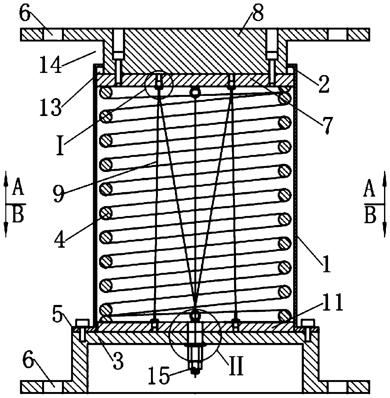
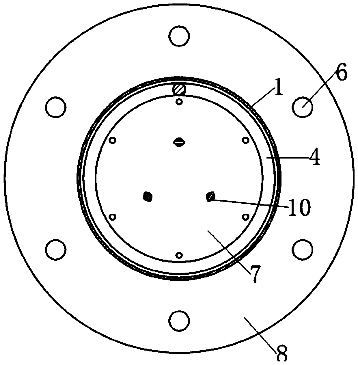
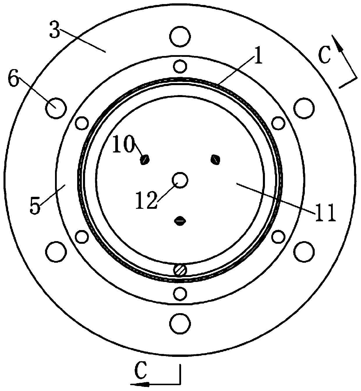
[0036] see Figure 1-5 , the damper described in this example is a vertical shock-isolation device (also known as a vertical shock-isolation support) for building anti-seismic, which includes a guide sleeve 1, a first end cover 2, a second end cover 3 , Cylindrical helical compression spring 4 and back pressure device.

[0037] see Figure 1~3 , the guide sleeve 1 is in the shape of a circular tube, its upper end radially shrinks inward to form a first end cover 2 with a guide hole in the center, and its lower end radially extends outward to form a flange 5 . The middle part of the second end cover 3 bulges upwards to form an inverted washbasin shape, and the surrounding edges are provided with mounting holes 6, and the guide sleeve 1 is fixed on the raised middle part by the flange plate 5 provided at the lower end. upper surface.

[0038] see Figure 1~3 , the driving member is composed of a dynamic pressure plate 7 and an upper connecting plate 8, wherein the upper conne...

example 2

[0056] see Figures 11 to 14 , the damper described in this example is also a vertical shock-isolation device for building anti-seismic, and on the basis of example 1, the following improvements are mainly made: (1) the preloaded steel wire rope 9 is increased by three to six; (2) replace the eyebolt 10 as the wire rope reversing element with a U-shaped member 16; (3) correspondingly change the described back pressure device to:

[0057] The back pressure device consists of six preloaded steel wire ropes 9, six U-shaped components 16 as wire rope direction changing elements, a floating back pressure steel plate 11, six eyebolts 10 fixing one end of the preloaded steel wire ropes 9 and one fixed The other end of the preloaded wire rope 9 is composed of a wire rope self-locking tensioning anchorage 15; wherein,

[0058] The floating anti-pressure steel plate 11 is arranged between the cylindrical helical compression spring 4 and the second end cover 3;

[0059] Six U-shaped memb...

example 3

[0064] see Figures 15-17 , this example is a damper used for seismic reinforcement of building structures, the damper includes a guide sleeve 1, the two ends of the guide sleeve 1 are respectively fixed with a first end cover 2 and a second end cover 3, and a cylindrical Helical compression spring 4, a driving member stretches into the guide sleeve 1 from the center of the first end cover 2 at one end of the guide sleeve and presses on the cylindrical helical compression spring 4; wherein the driving member is formed by the dynamic pressure plate 7 It is composed of a drive rod 17 integrated with it, and the end of the drive rod 17 is provided with a hinge hole 18 .

[0065] see Figure 15 The outer side of the second end cover 3 is symmetrically provided with two parallel lugs 19 integrally connected with it along the axis of the guide sleeve 1 , and the ends of the lugs 19 are also provided with hinged holes 18 .

[0066] see Figures 15-19 , the guide sleeve 1 is provid...


PUM


Abstract

The invention relates to a back pressure type spiral spring damper with adjustable initial rigidity. The back pressure type spiral spring damper is characterized in that a back pressure device is further arranged in a guide sleeve, wherein the back pressure device comprises three or more pre-compaction steel wire ropes, steel wire rope turning elements which are as many as the pre-compaction steel wire ropes, a steel wire rope self-locking tensioning anchorage device and a floating back pressure steel plate; the pre-compaction steel wire ropes are distributed in a central hole of a cylindrical spiral compression spring in a folding mode; one end of each pre-compaction steel wire rope is symmetrically fixedly arranged on the floating back pressure steel plate around the axis of the guide sleeve; the other end of each pre-compaction steel wire rope is turned back after passing through one opposite steel wire rope turning element and is paralleled to be a rope bundle, then, passes through the floating back pressure steel plate from a fixed point, which allows the axis of the guide sleeve to pass through, on the floating back pressure steel plate, and is fixedly arranged on a second end cover the steel wire rope self-locking tensioning anchorage device; and each pre-compaction steel wire rope is tensioned to tension needed for setting initial rigidity, so that the composite spring is clamped between a drive component and the floating back pressure steel plate all the time.

Description

technical field [0001] The invention relates to a building anti-vibration (or vibration) device, in particular to a damping device comprising a helical compression spring. Background technique [0002] A damper is a device that dissipates the energy of motion by providing resistance to motion. Since the 1970s, dampers have been gradually transferred from industries such as aerospace, aviation, military, guns, and automobiles to structural engineering such as buildings, bridges, and railways. Coil springs are widely used in devices such as shock isolation and shock absorption due to their variable stiffness characteristics in which the load and deformation are linearly related. Coil springs are classified according to the method of use, mainly including extension springs and compression springs, among which cylindrical helical compression springs are most commonly used in dampers. However, a specific cylindrical helical compression spring can only work in a compressed state...

Claims


Application Information

Patent Timeline
Patent Type & Authority Patents(China)
IPC IPC(8): F16F7/104
Inventor 谢韩涛刘汶津韩磊张少华
Owner NANJING DADE DAMPING TECH CO LTD
Why Eureka
Try Eureka