Small-size deep foundation pit supporting structure for pipe jacking construction

A deep foundation pit support, small size technology, applied in infrastructure engineering, excavation, construction, etc., can solve problems such as unsuitability

Active Publication Date: 2017-02-22
河南省水利勘测设计研究有限公司
View PDF6 Cites 16 Cited by
  • Summary
  • Abstract
  • Description
  • Claims
  • Application Information

AI Technical Summary

Problems solved by technology

However, for the sake of economy and saving investment, some pipe jacking foundation pits usually have a small inner diameter (only to meet the requirements of pipe jacking construction), so the conventional cantilever row pile support scheme is limited, and the underground geological conditions are complex, and the foundation pits located in the urban environment For the foundation pit, if there are many surrounding facilities (various pipelines, optical cables and buildings), it is not suitable to adopt the conventional support scheme combining anchor cables and inner supports for construction. Therefore, for such a small diameter (3-8 meters ) and a deep foundation pit with a depth greater than 8m (8~13m) needs to design a new support scheme to meet the requirements of safe construction

Method used


Image

  • Small-size deep foundation pit supporting structure for pipe jacking construction
  • Small-size deep foundation pit supporting structure for pipe jacking construction
  • Small-size deep foundation pit supporting structure for pipe jacking construction

Examples


Embodiment Construction

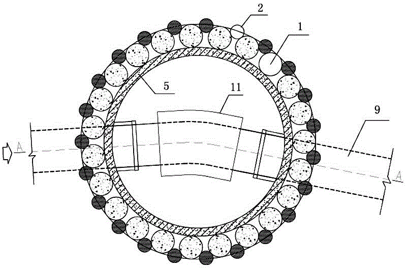
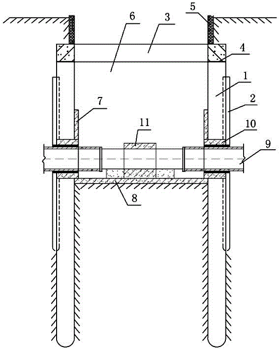
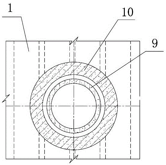
[0017] The small-sized deep foundation pit support structure used for pipe jacking construction according to the present invention is as follows: Figure 1-2 As shown, follow the specific steps below for construction:

[0018] The first step is to construct a plurality of bored piles 1 at intervals around the foundation pit determined on the ground to form a ring-shaped row of bored piles; during specific construction, the diameter and interval of the bored piles and the degree of support The depth is calculated and determined comprehensively based on the depth of the foundation pit, current geological conditions, surrounding loads, and groundwater characteristics. Under normal circumstances, the diameter of bored piles is generally initially planned to be 0.80m to 2m;

[0019] In the second step, according to the actually measured groundwater elevation, a high-pressure jet grouting pile 2 is constructed in the gap between two adjacent bored piles 1, wherein the pile body dia...


PUM


Abstract

The invention discloses a small-size deep foundation pit supporting structure for pipe jacking construction. The supporting structure is constructed through the steps that firstly, bored perfusion pile rows are constructed around the determined foundation pit position, a high-pressure jet grouting pile row is constructed in a gap formed between every two adjacent bored perfusion pile rows, a side slope is excavated from the ground, an annular crown beam is poured on the tops of the bored perfusion pile rows, asphalt felt is laid between the crown beam and pile bodies, and then a brick wall is built on the top of the crown beam; secondly, a foundation pit is excavated after the crown beam reaches the required strength, and after the foundation building surface meets the construction requirement, the side wall of the foundation pit and an inner lining (the position where a jacking pipe is arranged in a penetrating mode is reserved) of a bottom plate are poured with reinforced concrete; lastly, opening treatment is conducted on the jacking pipe, a second-stage reinforced concrete layer is built on the dismantling face, and after the later-period pipe jacking construction requirements are met, overall supporting structure construction is completed. According to the small-size deep foundation pit supporting structure for pipe jacking construction, a conventional cantilever pile supporting method is broken through, and the supporting structure arranged in the foundation pit in a finite space meets the supporting requirement of a surrounding complex environment; meanwhile, by combining the construction characteristics of pipe jacking construction, basic guarantee conditions are provided for normal and safe construction of pipe jacking engineering.

Description

technical field [0001] The invention relates to pipeline embedding construction technology, in particular to a small-sized deep foundation pit support structure for pipe jacking construction. Background technique [0002] Pipe jacking construction is non-excavation (or less excavation) pipeline (including urban underground water supply and drainage pipelines, natural gas and oil pipelines, communication cable pipelines, etc.) buried construction technology. This technology completely solves the problems of damage to urban buildings and the impact on road traffic during the pipeline burying construction process, and has more obvious advantages in stabilizing the soil layer and environmental protection. Under normal circumstances, for various pipeline crossing projects with a diameter of 1m~3m, especially in the urban environment and in order to protect the important ecology, green areas, rivers, buildings and other facilities on the surface from damage, trenchless constructio...

Claims


Application Information

Patent Timeline
Patent Type & Authority Applications(China)
IPC IPC(8): E02D17/04E02D17/08
CPCE02D17/04E02D17/08
Inventor 朱太山贾少燕姚高岭李玉娥杨华军王志军陈满圈李红涛姜辉曹捷魏珂黄杏成王春磊杨保军翁宛李洋范梦宇
Owner 河南省水利勘测设计研究有限公司
Why Eureka
Try Eureka