
Water retaining dam

A technology for retaining dams and backwater surfaces, which is applied in water conservancy projects, sea area projects, coastline protection, etc., and can solve problems such as troublesome operation, difficulty in success, and inability to lift gates, achieving the effects of convenient operation, stable support, and simple structure

Inactive Publication Date: 2017-02-22
安徽省六安恒源机械有限公司
View PDF8 Cites 5 Cited by
  • Summary
  • Abstract
  • Description
  • Claims
  • Application Information

AI Technical Summary

Problems solved by technology

However, the insertion and extraction of the positioning pins are manually operated on the shore through the steel hinge wires connected with the positioning pins. If the water level is submerged, it cannot be recognized by humans, and it is difficult to realize the action of installing the plug

Method used


Image

  • Water retaining dam
  • Water retaining dam
  • Water retaining dam

Examples


Embodiment Construction

[0011] Combine below Figure 1-Figure 5 The present invention is discussed in further detail.

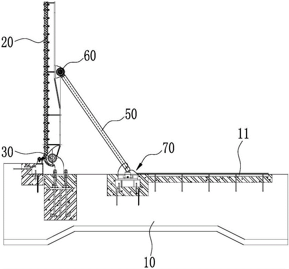
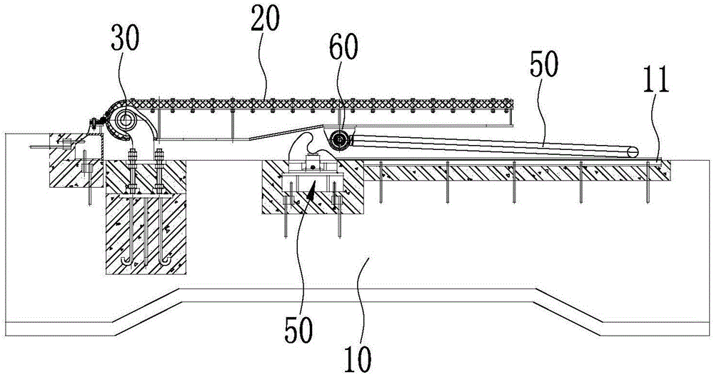
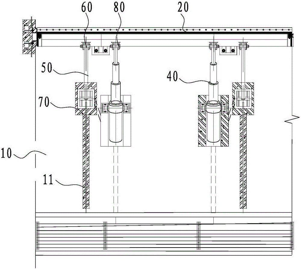
[0012] A retaining dam, comprising a ram 20, the lower part of the ram 20 is hinged to the support 10 by a first hinge shaft 30, a hydraulic cylinder 40 is arranged between the backwater surface of the ram 20 and the support 10, and the hydraulic cylinder 40 drives the ram 20 rotates around the first hinge shaft 30, and a support rod 50 is also provided between the backwater surface of the gate 20 and the support 10, and the upper end of the support rod 50 and the backwater surface of the gate 20 are hinged by the second hinge shaft 60, The rotation axis cores of the second hinge shaft 60 and the first hinge shaft 30 are located in the horizontal direction and are parallel to each other. A concave portion 71 is arranged on the fixed bracket 70. The opening of the concave portion 71 is arranged upward, and the lower end of the support rod 50 is placed in the concave portion 71 to for...


PUM


Abstract

The invention provides a water retaining dam which can support a gate and relieve supporting of the gate automatically and is reliable to operate. The dam comprises the gate; the lower part of the gate is hinged to a support seat through a first hinge shaft; hydraulic cylinders are arranged between the back surface of the gate and the support seat and drive the gate to rotate around the first hinge shaft; support rods are further arranged between the back surface of the gate and the support seat; upper ends of the support rods are hinged to the back surface of the gate through second hinge shafts; the second hinge shafts are parallel with the rotating shaft core direction of the first hinge shaft; a concave part is formed in a fixed clamping seat; an opening of the concave part is formed upwards; lower ends of the support rods are arranged in the concave part to realize limiting matching in the horizontal direction of the lower ends of the support rods; and the lower ends of the support rods are separated from the concave part to be in the free state. When the hydraulic cylinders act to jack up the gate, the lower ends of the support rods slide into the concave part in the fixed clamping seat to realize limiting in the horizontal direction; and when the gate is required to be opened for release water, the lower ends of the support rods slide out of the concave part in the fixed clamping seat, and the gate is turned backwards to lie down.

Description

technical field [0001] The invention relates to the technical field of water conservancy facilities, in particular to a retaining dam. Background technique [0002] At present, the bottom shaft rotating retaining dam used on the river gate dam of the urban water conservancy landscape project has higher safety, reliability and longer service life than the rubber dam, and has a small investment compared with the steel dam gate. The advantages of low maintenance cost have been recognized by everyone, especially widely used in small water conservancy landscape projects. The retaining dam is supported by a hydraulic cylinder, and the back of the ram with the bottom as the hinge axis is used to realize the purpose of raising and lowering the ram to block water and lowering the ram to discharge flood. After the lifting dam is raised, it is supported by the sliding support rods hinged on the back of the gate to form a stable supporting dam. [0003] The retaining dam with the pate...

Claims


Application Information

Patent Timeline
IPC IPC(8): E02B7/00E02B7/40
CPCE02B7/00E02B7/40
Inventor 陈荣娜黄振东袁家宝李登国王之辉
Owner 安徽省六安恒源机械有限公司
Learn More