
Lubricating device for draw-bar guide sleeves of moving mold plate of injection molding machine and system thereof

A tie rod guide bushing and lubricating system technology, which is applied in the field of the tie rod guide bushing lubrication device and its system for injection molding motorized formwork, can solve the problems of high internal pressure, waste of lubricating oil, and inability to detect it intuitively, so as to reduce pollution and wear. Effect

Inactive Publication Date: 2017-02-22
WUXI HAITIAN MACHINERY
View PDF5 Cites 1 Cited by
  • Summary
  • Abstract
  • Description
  • Claims
  • Application Information

AI Technical Summary

Problems solved by technology

[0004] In the prior art, because the demand for lubricating grease in the cavity of the movable template cannot be accurately estimated within a certain period, and it is impossible to visually detect whether it has been filled up, sometimes too much lubricating grease is injected, resulting in excessive internal pressure and the lubricating grease Squeeze out from the dust-proof rings at both ends, on the one hand, it will pollute the mold clamping area, and on the other hand, it will also cause waste of lubricating grease
At the same time, during the operation of the template, the guide copper sleeve will also rub against the pull rod, and impurities such as copper powder will enter the lubricating grease on the inner wall of the guide copper sleeve. Reduced lubricity

Method used


Image

  • Lubricating device for draw-bar guide sleeves of moving mold plate of injection molding machine and system thereof
  • Lubricating device for draw-bar guide sleeves of moving mold plate of injection molding machine and system thereof
  • Lubricating device for draw-bar guide sleeves of moving mold plate of injection molding machine and system thereof

Examples


Embodiment Construction

[0030] The technical solutions of the present invention will be clearly and completely described below in conjunction with the accompanying drawings. Apparently, the described embodiments are some of the embodiments of the present invention, but not all of them. Based on the embodiments of the present invention, all other embodiments obtained by persons of ordinary skill in the art without making creative efforts belong to the protection scope of the present invention.

[0031] In the description of the present invention, it should be noted that the terms "center", "upper", "lower", "left", "right", "vertical", "horizontal", "inner", "outer" etc. The indicated orientation or positional relationship is based on the orientation or positional relationship shown in the drawings, and is only for the convenience of describing the present invention and simplifying the description, rather than indicating or implying that the referred device or element must have a specific orientation, ...


PUM


Abstract

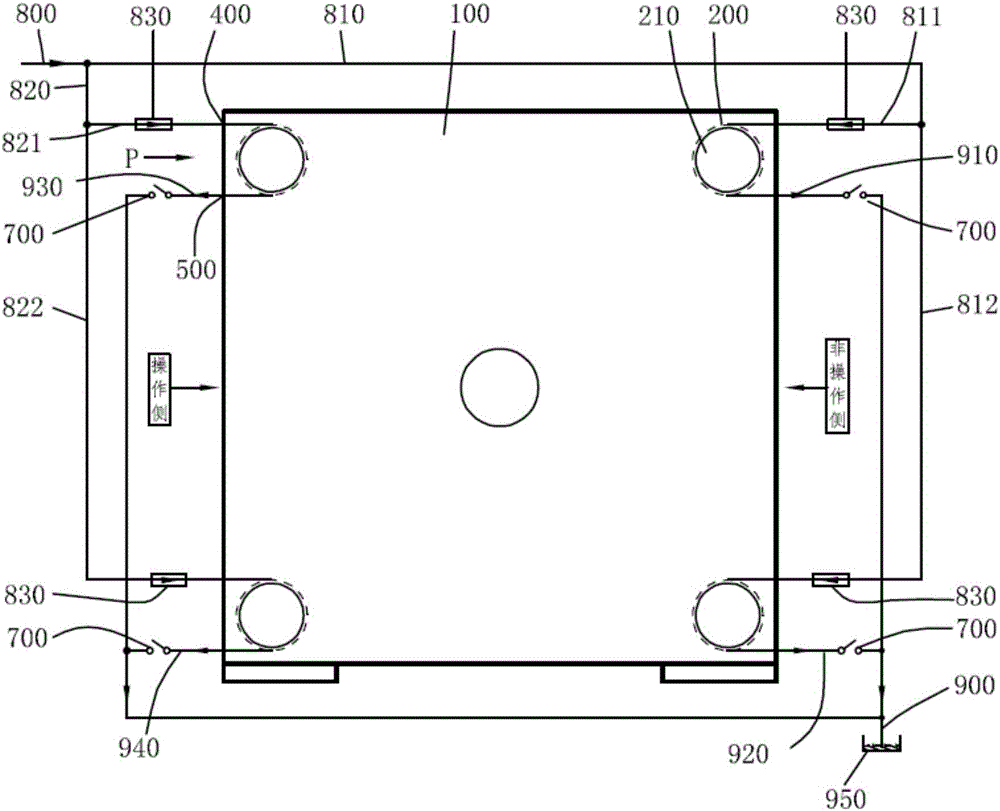
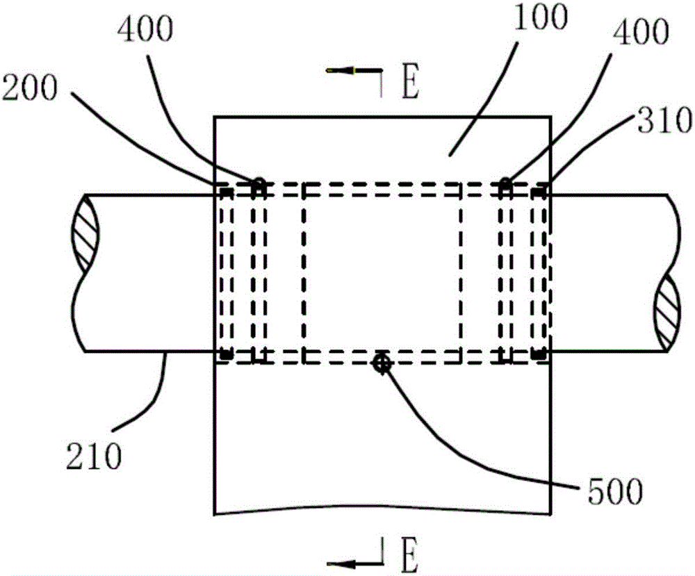
The invention provides a lubricating device for draw-bar guide sleeves of a moving mold plate of an injection molding machine and a system thereof and relates to the technical field of lubrication of the moving mold plate of the injection molding machine. The device comprises the movable mold plate and the guide sleeves; draw bar through holes are formed in the movable mold plate, and the guide sleeves sleeve the inner sides of two ends of each of the draw bar through holes; oil inlet through holes are formed in the upper side walls, close to ports on two sides, of each of the draw bar through holes, an oil through hole is formed in the side wall of each of the guide sleeves, and the oil inlet through holes communicate with the oil through holes; oil outlet through holes are formed along the lower side walls of the axial middle part of each of the draw bar through holes; and switches are mounted on the outer sides of the oil outlet through holes. The lubricating device provided by the invention solves the technical problem that the adding amount of grease cannot be examined and impurities in the movable mold plate cannot be immediately discharged when lubricating grease is added into a conventional movable mold plate. By adopting the device and the system thereof, whether the filling amount is full or not when the lubricating grease is filled can be detected. Waste oil in a lubricating chamber can be discharged by controlling the switches before the lubricating grease is filled or the lubricating grease is being filled.

Description

technical field [0001] The invention relates to the technical field of lubrication of injection molding motorized templates, in particular to a lubricating device and a system for injection molding motorized template tie rod guide sleeves. Background technique [0002] The sliding guide sleeve is used as the guide between the inner moving platen and the tie rod of the injection molding machine, and the outside is lubricated by lubricating grease through the lubricating grease nipple or the lubricating pipeline. The guide part of each tie rod on the movable formwork adopts two guide sleeves, and a dust-proof ring is arranged outside the guide sleeve to prevent dust. The main function is to prevent impurities on the surface of the tie rod from entering the guide sleeve. An oil seal will also be provided to prevent lubricating grease from extruding from the end face of the guide sleeve. [0003] Since the oil film will be attached to the surface of the tie rod during each move...

Claims


Application Information

Patent Timeline
Patent Type & Authority Applications(China)
IPC IPC(8): B29C45/83
CPCB29C45/83
Inventor 王闯惠杰宋碧君
Owner WUXI HAITIAN MACHINERY
Learn More