A grabbing method with claw structure for automatic grabbing of engine casing

A technology for engine housings and grippers, applied in the direction of manipulators, program-controlled manipulators, chucks, etc., can solve problems such as easy deformation, high cost, and large volume, and achieve the goals of ensuring positioning accuracy, improving adaptability, and increasing gripping force Effect

Active Publication Date: 2019-03-19
宜昌长机科技有限责任公司
View PDF9 Cites 0 Cited by
  • Summary
  • Abstract
  • Description
  • Claims
  • Application Information

AI Technical Summary

Problems solved by technology

Due to the complex shape and structure of the engine and the special processing technology, the ordinary manipulator structure cannot carry out its automatic grabbing; and the irregular box structure of the engine casing cannot accurately calculate or control its center of gravity during the grabbing process. Medium stability cannot be well guaranteed; in addition, the outer shell of the engine is generally made of aluminum alloy precision casting, which is large in size, poor in rigidity, and easy to deform. Ordinary manipulators cannot guarantee its gripping force; finally, in the entire engine production line, it is often necessary to deploy manipulators at multiple stations, and special manipulators basically need to be imported from abroad, which is costly

Method used


Image

  • A grabbing method with claw structure for automatic grabbing of engine casing
  • A grabbing method with claw structure for automatic grabbing of engine casing
  • A grabbing method with claw structure for automatic grabbing of engine casing

Examples


Embodiment 1

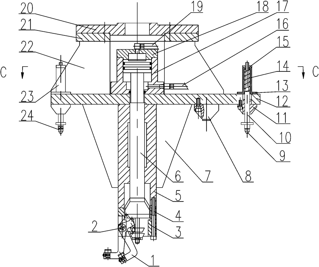
[0048] Such as Figure 1-9, a claw structure for automatic grabbing of the engine casing, which includes a plurality of claw heads 1, the claw heads 1 are hinged on the head of the claw head seat 3 through a pin shaft 2, and the claw head seat 3 is fixedly installed on The end of the sliding sleeve 5, the sliding sleeve 5 is fixed on the lower end surface of the bottom plate 12, the sliding sleeve 5 is fitted with a piston rod 6, and the bottom end of the piston rod 6 cooperates with the claw head 1 to control the claw head 1, the top of the piston rod 6 is matched with the oil cylinder seat 17, and the oil cylinder seat 17 is fixed on the upper surface of the bottom plate 12, and the bottom end of the oil cylinder seat 17 is processed with a No. 1 oil inlet 16. An oil cylinder cover 18 is installed on the top of the oil cylinder block 17, and the top of the oil cylinder cover 18 is processed with a No. 2 oil inlet 19. The top of the bottom plate 12 is equipped with a top plat...

Embodiment 2

[0060] Using any claw structure to grab the engine housing method, it includes the following steps:

[0061] S1: Fix the claw structure on the head of the mechanical arm through the flange 20, and connect the No. 1 oil inlet 16 and the No. 2 oil inlet 19 to the hydraulic system respectively;

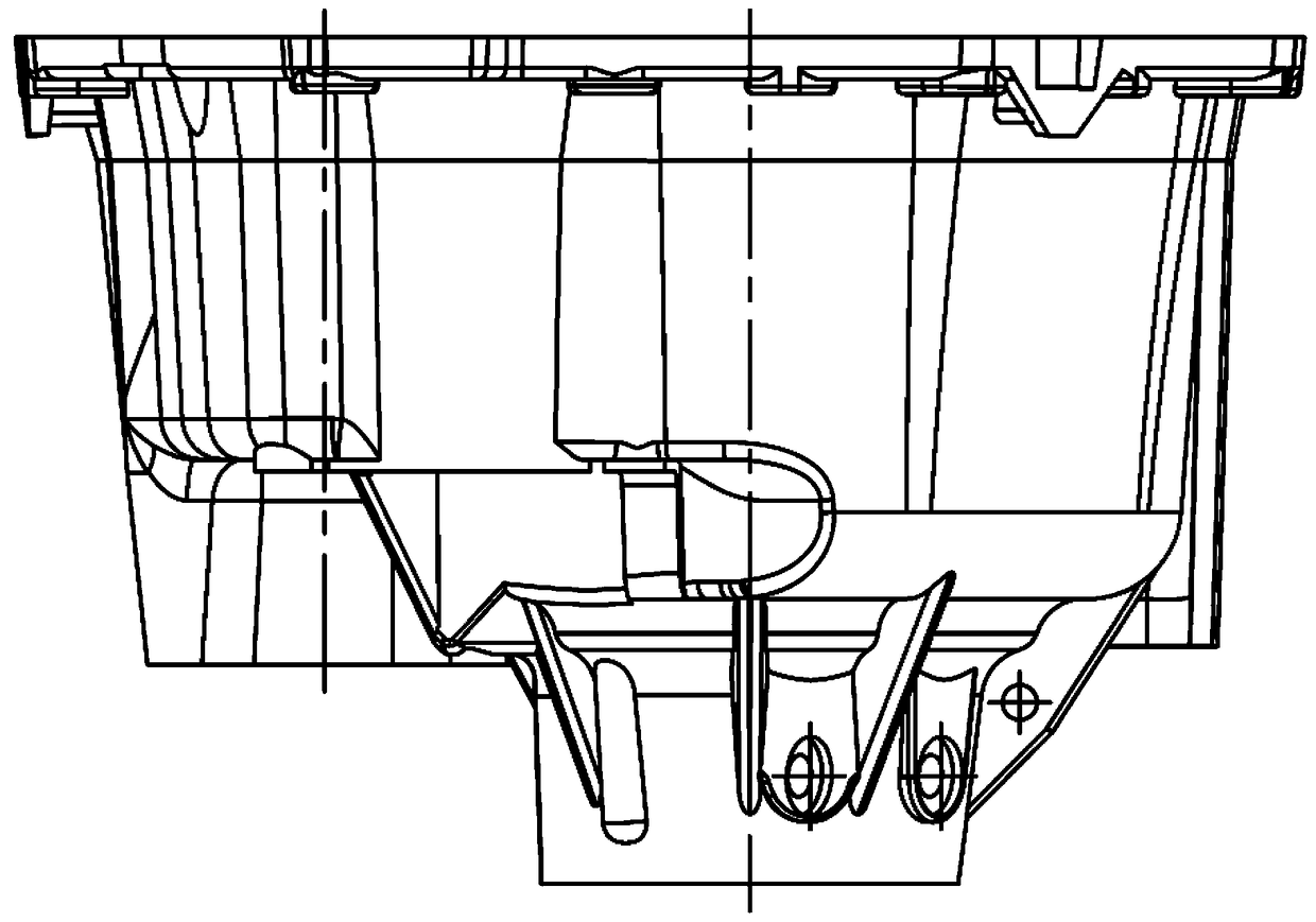
[0062] S2: At the beginning, the claw head 1 is in the folded state, and the mechanical arm drives the gripping structure to insert the sliding sleeve 5 of the claw head 1 into the center hole of the engine housing, so as to ensure that the round pin head 9 and the diamond pin 24 on the bottom surface of the bottom plate 12 are in line with the The two positioning holes on the engine casing are matched and positioned, while ensuring that the three end face positioning blocks 8 are positioned and matched with the end face of the engine casing;

[0063] S3: No. 2 oil inlet 19 enters oil, pushes the piston rod 6 to move downward, the lower limit block 605 of the head of the piston rod 6 wit...


PUM


Abstract

The invention relates to a claw structure and a grabbing method for automatically grabbing an engine casing. The claw head is hinged on the head of the claw head seat through a pin shaft, and the claw head seat is fixedly installed at the end of a sliding sleeve, and the inside of the sliding sleeve is slidably fitted. A piston rod is installed, and the top of the piston rod is matched with the oil cylinder seat, and the oil cylinder seat is fixed on the upper end surface of the bottom plate. The bottom end of the oil cylinder seat is processed with a No. 1 oil inlet, and an oil cylinder is installed on the top of the oil cylinder seat The top of the oil cylinder head is processed with No. 2 oil inlet, the top of the bottom plate is installed with a top plate through multiple sets of supporting ribs, the top plate is fixedly installed with a flange, and the bottom plate is also installed with a buffer Positioning means. This kind of grabbing structure realizes automatic grabbing, automatic loading and unloading functions through special grippers; it meets the requirements of accurate positioning, fast grabbing, and high reliability; it can be used for production line loading, milling, etc. The station conversion during each processing procedure.

Description

technical field [0001] The invention belongs to the field of auxiliary processing devices for engine casings, and in particular relates to a claw structure and a grabbing method for automatically grabbing engine casings, which are suitable for processing engine casings in industries such as automobiles, aerospace, and military affairs. Background technique [0002] Engines are vital components in automotive, aerospace, military, and more. The engine casing wraps the core components to provide stable and continuous power output for the main engine, and is an important part of the entire component. The engine casing is often made of aluminum alloy precision casting, which has the characteristics of light weight, complex shape structure, poor rigidity and easy deformation. The machining process of the engine shell is complicated, the process is long, and there are many stations. [0003] In actual production, in order to improve processing efficiency, realize automation, unma...

Claims


Application Information

Patent Timeline
Patent Type & Authority Patents(China)
IPC IPC(8): B25J15/10B25J9/14B23Q7/04
CPCB23Q7/043B25J9/146B25J15/10
Inventor 乔凌云代国辉樊强军陶博
Owner 宜昌长机科技有限责任公司
Why Eureka
Try Eureka