
Clutch structure for mechanical arm

A technology of a mechanical arm and a hydraulic pump is applied in the field of the clutch structure of the mechanical arm, which can solve the problems of inability to locate and rotate with less effort, backward clutch structure, and single function.

Inactive Publication Date: 2017-02-22
ANHUI ZHILIANG INVESTMENT GRP
View PDF0 Cites 0 Cited by
  • Summary
  • Abstract
  • Description
  • Claims
  • Application Information

AI Technical Summary

Problems solved by technology

[0002] At present, in some factories and enterprises, it is often necessary to carry some large objects. Because the objects are large or there is no suitable force point, there are certain hidden dangers and limitations when carrying out manual transportation. Therefore, there are certain limitations in the market. Some mechanical arms have appeared, but they are simple in structure and single in function. Moreover, ordinary mechanical arms do not have hydraulic pumps and cannot be lifted. Moreover, the clutch structure is relatively backward, and they cannot be positioned and rotated effortlessly. Therefore, it is necessary to improve the mechanical arms. manufacturing technology

Method used


Image

  • Clutch structure for mechanical arm
  • Clutch structure for mechanical arm
  • Clutch structure for mechanical arm

Examples


Embodiment Construction

[0016] The following will clearly and completely describe the technical solutions in the embodiments of the present invention with reference to the accompanying drawings in the embodiments of the present invention. Obviously, the described embodiments are only some, not all, embodiments of the present invention.

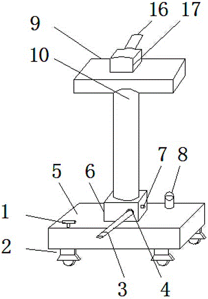
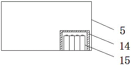
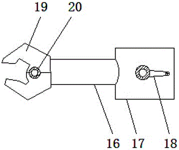
[0017] refer to Figure 1-4 , a clutch structure for a mechanical arm, including a fixed base 5 and a hydraulic pump 6; a brake 1 is arranged on the upper left side of the fixed base 5, and a connecting groove 4 is opened on the hydraulic pump 6, and the connecting groove 4 is sleeved with a The pressure rod 3 and the middle part of the right side of the hydraulic pump 6 are threadedly connected with a pressure relief knob 7, and the upper part of the hydraulic pump 6 is connected with a support column 10, and the inside of the support column 10 is sleeved with a lifting rod 11, and the top of the lifting rod 11 is connected in rotation. There is a support plate 9, a...


PUM


Abstract

The invention discloses a clutch structure for a mechanical arm. The clutch structure comprises a fixed base and a hydraulic pump. A brake part is arranged on the left side of the upper part of the fixed base. A connecting groove is formed in the hydraulic pump. A pressure rod is sleeved by the connecting groove. A pressure release turn button is in threaded connection with the middle of the right side of the hydraulic pump. A supporting pillar is connected to the upper part of the hydraulic pump. A lifting rod is sleeved by the supporting pillar. A supporting plate is rotationally connected with the top end of the lifting rod. A piston is arranged in the hydraulic pump. A pressure sensor is fixedly connected with the right side of the bottom end of the hydraulic pump. A storage battery fixing box is fixedly connected with the right side of the bottom end of the fixed base through a screw. A control box is welded in the middle of the supporting plate. The mechanical arm is rotationally connected with the left side of the control box. Clutch clamp heads are mounted on the left side of the mechanical arm. According to the clutch structure, the hydraulic pump is mounted, the lifting rod is controlled under the hydraulic action, and the hydraulic pump cooperates with the supporting plate to achieve a supporting effect.

Description

technical field [0001] The invention relates to the technical field of mechanical equipment, in particular to a clutch structure for a mechanical arm. Background technique [0002] At present, in some factories and enterprises, it is often necessary to carry some large objects. Because the objects are large or there is no suitable force point, there are certain hidden dangers and limitations when carrying out manual transportation. Therefore, there are certain limitations in the market. Some mechanical arms have appeared, but they are simple in structure and single in function. Moreover, ordinary mechanical arms do not have hydraulic pumps and cannot be lifted. Moreover, the clutch structure is relatively backward, and they cannot be positioned and rotated effortlessly. Therefore, it is necessary to improve the mechanical arms. manufacturing technology. Contents of the invention [0003] The object of the present invention is to propose a clutch structure for a mechanical...

Claims


Application Information

Patent Timeline
Patent Type & Authority Applications(China)
IPC IPC(8): B25J5/00B25J19/06
CPCB25J5/007B25J19/061
Inventor 王卫华
Owner ANHUI ZHILIANG INVESTMENT GRP
Learn More