Back tool clamp of radiator

A tooling fixture and radiator technology, applied in the field of tooling fixtures, can solve the problems of cumbersome use and low clamping efficiency, and achieve the effect of simple use and high clamping efficiency

Inactive Publication Date: 2017-02-22
WUXI TAICHANG PRECISION MACHINERY CO LTD
View PDF8 Cites 4 Cited by
  • Summary
  • Abstract
  • Description
  • Claims
  • Application Information

AI Technical Summary

Problems solved by technology

[0003] In view of the above-mentioned problems, the present invention provides a fixture for the back of the radiator, which can solve the technical problems that the existing fixture is cumbersome to use when clamping the radiator, and the clamping efficiency is low

Method used


Image

  • Back tool clamp of radiator
  • Back tool clamp of radiator
  • Back tool clamp of radiator

Examples


Embodiment Construction

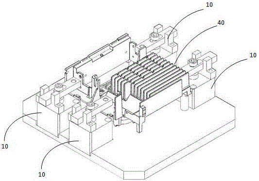
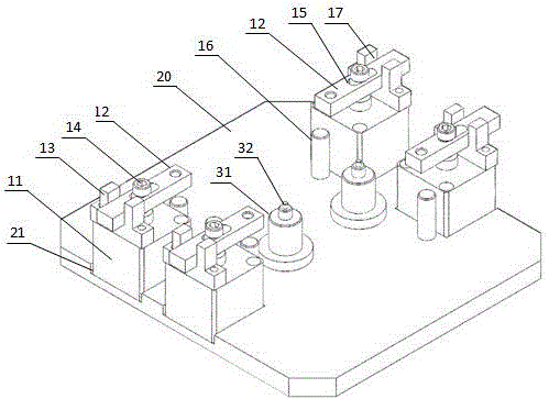
[0014] Such as Figure 2~Figure 3 As shown, it includes a bottom plate 20. Two clamping mechanisms 10 are provided on both sides of the bottom plate 20. The clamping mechanism 10 includes an air cylinder 11, a pressing plate 12, a guide seat 13 and a bolt 14. The pressing plate 12 is provided with a strip through groove 15 , The head of the bolt 14 is press-fitted on the upper end surface of the pressure plate 12, and its screw part passes through the strip groove 15 and then is threadedly connected with the piston rod of the cylinder 11. One end of the pressure plate 12 is threadedly connected with a pressure head (not shown in the figure) ). The other end is slidably connected with the sliding groove 17 of the guide seat, the bottom plate 20 is provided with a support column 16 that matches the pressure head, and the guide seat 13 is fixed on the cylinder 11;

[0015] The bottom plate 20 is also provided with a positioning mechanism corresponding to the through hole at the bott...


PUM


Abstract

The invention provides a back tool clamp of a radiator, and the back tool clamp can solve the technical problems that an existing clamp is relatively complex in use for clamping the radiator and is low in clamping efficiency. The back tool clamp comprises a bottom plate. The back tool clamp is characterized in that clamping mechanisms are separately arranged at the two sides of a bottom plate, wherein each clamping mechanism comprises an air cylinder, a pressure plate, a guide base and a fixed part; one end of each pressure plate is used for pressing the radiator, and the other end of each pressure plate is in sliding connection with a slide slot of the corresponding guide base; a strip-shaped through slot is formed each the pressure plate; one end of each fixed part passes through the strip-shaped through slot for fixing the corresponding pressure plate to the end part of the piston rod of the corresponding air cylinder; each fixed part is detachably connected with the piston rod of the corresponding air cylinder; each guide base is fixedly arranged on the bottom plate or the corresponding air cylinder; and a positioning mechanism which corresponds to the through hole in the bottom of the radiator is further arranged on the bottom plate.

Description

Technical field [0001] The invention relates to the field of tooling fixtures, in particular to the backside tooling fixtures of radiators. Background technique [0002] A radiator 40 whose structure is as figure 1 As shown, the surface is usually processed in casting. Although the existing clamp can realize the effective clamping of the radiator, each component constituting the clamp needs to be manually positioned and assembled every time it is used, which is cumbersome to use and low in clamping efficiency. Summary of the invention [0003] In view of the above-mentioned problems, the present invention provides a tooling fixture for the back of the radiator, which can solve the technical problems of cumbersome use of the existing fixture when clamping the radiator and low clamping efficiency. [0004] The technical solution is as follows, which includes a bottom plate, characterized in that: two sides of the bottom plate are respectively clamped, the clamping mechanism includes ...

Claims


Application Information

Patent Timeline
Patent Type & Authority Applications(China)
IPC IPC(8): B23Q3/08
CPCB23Q3/062B23Q3/08B23Q2703/04
Inventor 陈建华
Owner WUXI TAICHANG PRECISION MACHINERY CO LTD
Why Eureka
Try Eureka