
A steel sheet clamping device for laser cutting

A clamping device and laser cutting technology, applied in laser welding equipment, welding equipment, metal processing equipment, etc., can solve the problem of inability to guarantee the flatness and stability of the steel sheet, inconvenient manual cleaning of waste, time-consuming and laborious clamping process, etc. problem, to achieve the effect of convenient cleaning and recycling waste, simple structure and convenient operation

Active Publication Date: 2018-08-24
山东颐杰鸿丰能源装备有限公司
View PDF6 Cites 1 Cited by
  • Summary
  • Abstract
  • Description
  • Claims
  • Application Information

AI Technical Summary

Problems solved by technology

[0004] For this reason, the technical problem to be solved by the present invention is that the clamping process of the steel sheet clamping device used for steel sheet laser cutting in the prior art is time-consuming and laborious, the work efficiency is low, and the flatness and stability of the steel sheet cannot be guaranteed. low, and the temperature of the generated waste is high, it is inconvenient to manually clean up the waste, so a steel sheet clamping device for laser cutting is proposed

Method used


Image

  • A steel sheet clamping device for laser cutting
  • A steel sheet clamping device for laser cutting
  • A steel sheet clamping device for laser cutting

Examples


Embodiment Construction

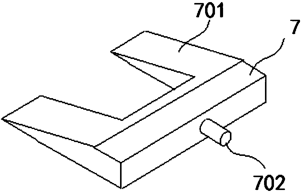
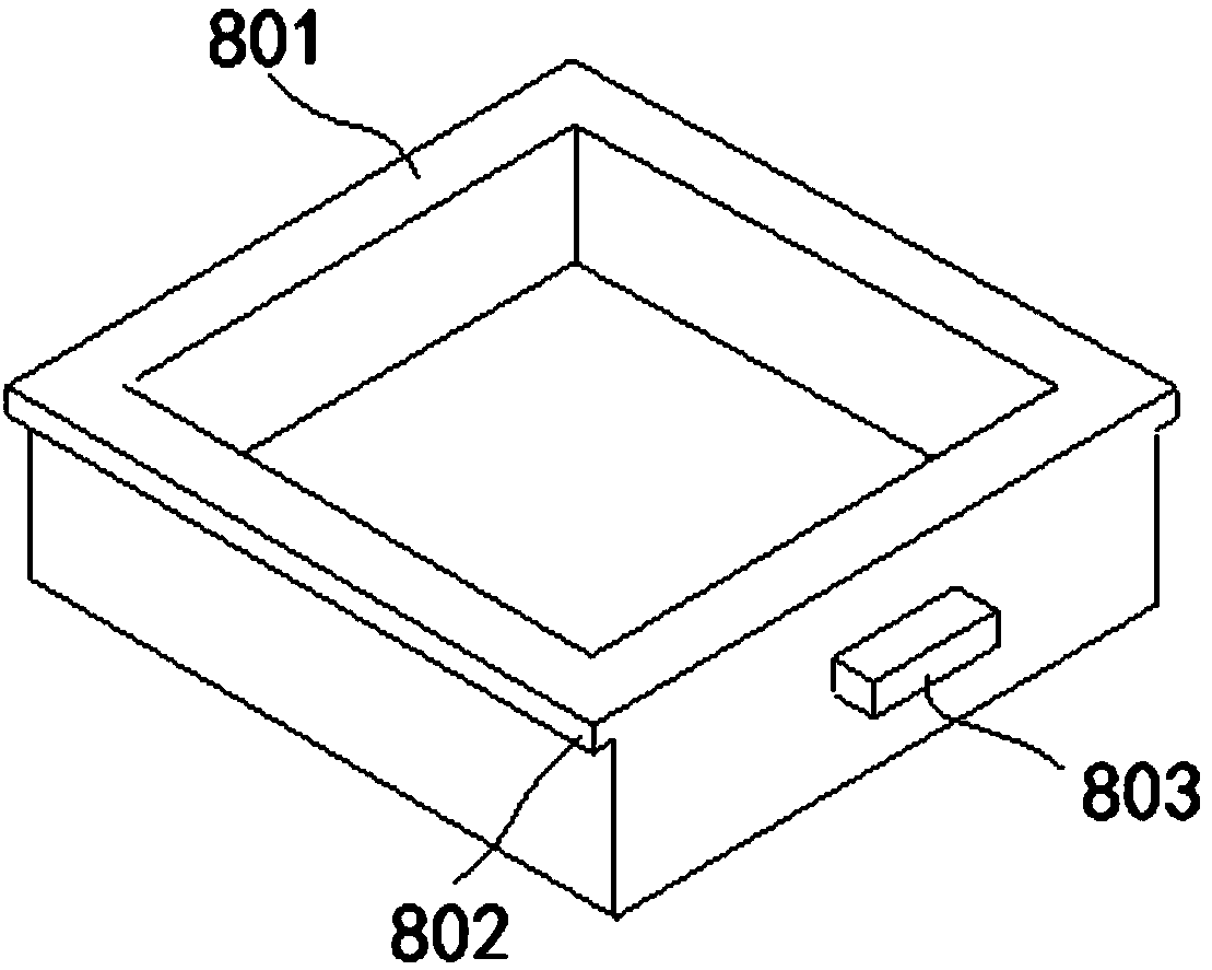
[0027] Such as figure 1 As shown, the steel sheet clamping device for laser cutting of the present invention includes:

[0028] Base 1, the center of the base 1 is formed with a first machining hole 101 that runs through the up and down direction of the base 1, and the bottom of the base 1 is formed with a through groove 102 that runs through the front and rear directions of the base 1, and the through groove Sliding grooves 103 are provided on both sides of the top of 102 .

[0029] The first bump 2 is formed on three sides of the base 1 . The first protrusion 2 is a rectangular protrusion, and the upper end surface of the first protrusion 2 is flush with the upper end surface of the base 1 .

[0030] The upper pressing plate 3 is arranged above the base 1 , and the center of the upper pressing plate 3 is formed with a second processing hole 301 penetrating the upper and lower directions of the upper pressing plate 3 . The diameter of the first processing hole 101 is not g...


PUM


Abstract

The invention discloses a steel sheet clamping device for laser cutting. The steel sheet clamping device comprises a base, a first bump, an upper pressure plate, a second bump, a guide post, a compression spring, a wedge block and a waste box. The device can conveniently clamp and fix a steel sheet and can realize position adjustment and unloading of the steel sheet; the operation is convenient, the working efficiency is high, the flatness and stability of the steel sheet are guaranteed, and the cutting quality is high; and moreover, through a waste tank at the lower end of the base, the waste can be conveniently cleared and recycled, and the whole laser cutting device is protected from smog. The device has the advantages of simple structure, convenience in operation, high processing efficiency and high processing quality.

Description

Technical field: [0001] The invention belongs to the technical field of laser cutting, in particular to a steel sheet clamping device for laser cutting. Background technique: [0002] Laser cutting is the use of high-power-density laser beams to irradiate materials, so that the materials are quickly heated to the vaporization temperature, and evaporate to form holes. As the beam moves to the material, the holes continuously form narrow (such as about 0.1mm) slits, and the process is completed. Cutting of material. Laser cutting is one of the thermal cutting methods. Laser cutting can be divided into four categories: laser vaporization cutting, laser melting cutting, laser oxygen cutting, and laser scribing and controlled fracture. It has the advantages of good cutting quality, high cutting efficiency, and fast cutting speed. It is a commonly used thermal cutting method for some sheet metal parts. [0003] In the prior art, the positioning of the steel sheet during laser c...

Claims


Application Information

Patent Timeline
Patent Type & Authority Patents(China)
IPC IPC(8): B23K26/38B23K26/70
CPCB23K26/38B23K26/702
Inventor 叶芳
Owner 山东颐杰鸿丰能源装备有限公司
Learn More