
Method and system for controlling synchronous scanning of body scanner

A technology of synchronous scanning and control method, applied in the field of human body scanning, can solve problems such as being unfavorable for portable equipment and rapid assembly, increasing equipment hardware complexity, increasing equipment production cost, etc., to reduce hardware complexity, improve synchronization accuracy, The effect of improving quality

Inactive Publication Date: 2017-02-22
XIAN SUANIER ELECTRONICS TECH
View PDF6 Cites 5 Cited by
  • Summary
  • Abstract
  • Description
  • Claims
  • Application Information

AI Technical Summary

Problems solved by technology

[0002] Three-dimensional human body scanning technology scans the whole body or part of the human body through the body scanner to form images or records of the human body, which can be widely used in various fields, such as clothing design, etc. Although the existing body scanners have improved the measurement of human body parameters Speed ​​improves the efficiency of subsequent clothing design and manufacturing. However, since the body scanner obtains human body parameters by taking pictures from multiple angles and different camera devices, the synchronization problem between each camera device seriously affects the final overall characteristics.
This method requires the trigger source and all devices to be connected through lines, which increases the complexity of the device hardware, increases the production cost of the device, and is not conducive to the portability and rapid assembly of the device.

Method used


Image

  • Method and system for controlling synchronous scanning of body scanner
  • Method and system for controlling synchronous scanning of body scanner
  • Method and system for controlling synchronous scanning of body scanner

Examples


Embodiment Construction

[0036] The present invention will be further described below in conjunction with the accompanying drawings.

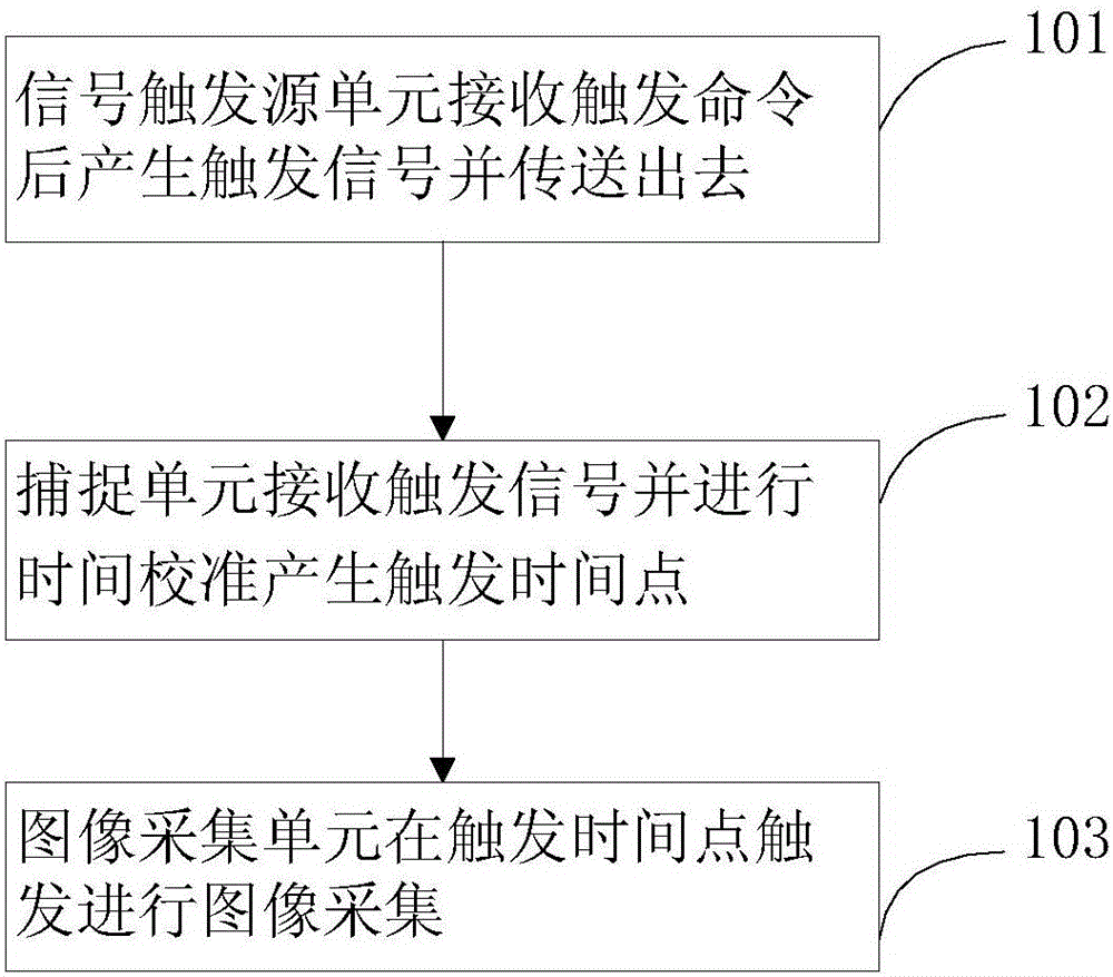
[0037] see figure 1 , which is a flowchart of a synchronous scanning control method for a body scanner provided by the present invention.

[0038] like figure 1 Shown, a kind of body scanner synchronous scanning control method is characterized in that, comprises the following steps:

[0039] Step 101, after receiving the trigger command, the signal trigger source unit generates a trigger signal and transmits it;

[0040] Step 102, the capture unit receives the trigger signal and performs time calibration to generate a trigger time point;

[0041] Step 103, the image acquisition unit triggers image acquisition at the trigger time point.

[0042] The present invention controls the synchronization between the image acquisition units by using the signal source trigger unit and the capture unit, which can effectively avoid the failure of the image acquisition unit to pe...


PUM


Abstract

The invention discloses a system for controlling synchronous scanning of a body scanner. The system is characterized by comprising the steps that a signal triggering source unit generates a triggering signal and sends out the signal after receiving a triggering command; a capture unit receives the triggering signal and carries out time calibration to produce a triggering time point; an image capturing unit is triggered at the triggering time point to conduct image capturing. The invention also discloses a system for controlling synchronous scanning of the body scanner. The controlling system comprises the signal triggering source unit which is used for receiving the triggering command and generating the triggering signal, the capture unit which is used for receiving the triggering signal sent by the signal triggering source unit and carrying out demodulation and calibration on the triggering signal and the image capturing unit which conducts image capturing according to the triggering time point after the demodulation and calibration as well as finishes the synchronization of the image capturing unit. The method and the system for controlling synchronous scanning of the body scanner can effectively avoid that the image capturing unit can not capture images synchronously due to delay of positions and receiving signals between the image capturing units and other situations, thus improving the quality of scanning.

Description

technical field [0001] The invention relates to the technical field of human body scanning, in particular to a method and system for controlling synchronous scanning of a human body scanner. Background technique [0002] Three-dimensional human body scanning technology scans the whole body or part of the human body through the body scanner to form images or records of the human body, which can be widely used in various fields, such as clothing design, etc. Although the existing body scanners have improved the measurement of human body parameters The speed improves the efficiency of subsequent clothing design and manufacturing. However, since the body scanner obtains human body parameters by taking pictures with different camera devices from multiple angles, the synchronization problem between each camera device seriously affects the final overall characteristics. [0003] At present, the image capture synchronization of multiple image capture units of the existing 3D human b...

Claims


Application Information

Patent Timeline
Patent Type & Authority Applications(China)
IPC IPC(8): A41H1/00
CPCA41H1/00
Inventor 杨少毅褚智威骆必争王强拜宏伟王邦全巨宇龙魏琳
Owner XIAN SUANIER ELECTRONICS TECH
Learn More