Automatic fixed-point fertilization starting hammer
An automatic and pneumatic hammer technology, applied in the field of urban greening and garden maintenance equipment, can solve the problems of small area occupied by trees, cumbersome operation, low work efficiency, etc., achieve convenient disassembly and replacement, simple device structure, and improve work efficiency Effect
- Summary
- Abstract
- Description
- Claims
- Application Information
AI Technical Summary
Problems solved by technology
Method used
Image
Examples
Embodiment 1
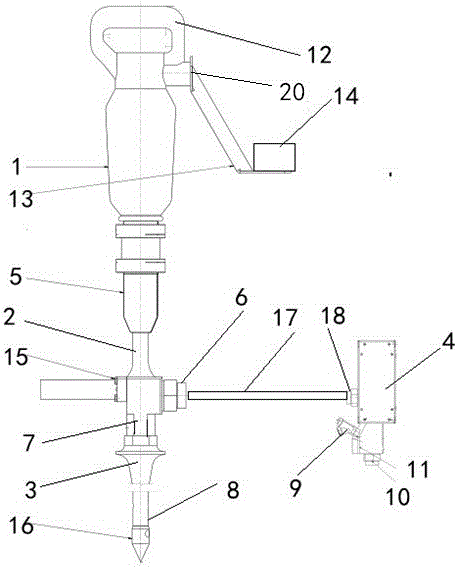
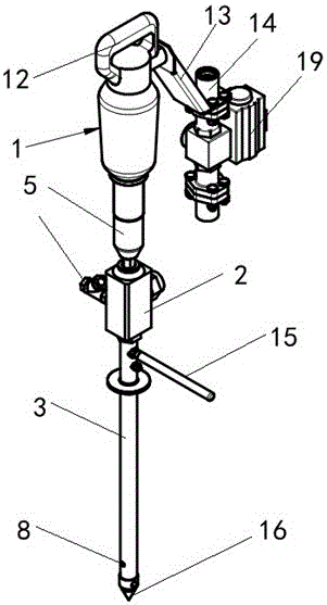
[0016] Embodiment 1: as figure 1 , 2 A starting hammer for automatic fixed-point fertilization is shown. The starting hammer includes an impact pneumatic hammer 1, a connecting rod 2, a drilling needle 3, and a pneumatic switching valve 4. The drilling needle 3 is fixedly installed on the connecting rod 2 Below, the bottom of the impact pneumatic hammer 1 is provided with a connecting sleeve 5, the top of the connecting rod 2 is movably installed in the connecting sleeve 5, and the inside of the drilling needle 3 is provided with a hollow air pressure feeding pipeline 7, The bottom of the drilling needle 3 is provided with a discharge port 8, and the connecting rod 2 is provided with a feed pipe 6, and the feed pipe 6 is respectively connected to the pneumatic feed pipeline 7 and the pneumatic switching valve 4, and the pneumatic switching The valve 4 is provided with a high-pressure gas feed pipe 9, a fertilizer feed pipe 10 and a comprehensive discharge pipe 18, and the com...
Embodiment 2
[0017] Embodiment 2: as figure 1 , 2 As shown, the top of the impact pneumatic hammer 1 is provided with a handle structure 12 and an air pressure input pipe 20, and the inner side of the handle structure 12 is provided with a pneumatic hammer control switch; the air pressure input pipe 20 is mainly used to provide power for the impact pneumatic hammer 1, through The switch on the handle structure 12 is controlled, and the switch is convenient and easy to operate.
Embodiment 3
[0018] Embodiment 3: as figure 1 , 2 As shown, the side of the handle structure 12 is provided with a control link 13, and the control link 13 is provided with an operation switch 14 and an air pressure control valve 19. The control valve 19 controls the switch of the air pressure input pipe 20 to prevent misoperation by the operator.
PUM
 Abstract
Description
Claims
Application Information
 - R&D Engineer
- R&D Manager
- IP Professional
- Industry Leading Data Capabilities
- Powerful AI technology
- Patent DNA Extraction
Browse by: Latest US Patents, China's latest patents, Technical Efficacy Thesaurus, Application Domain, Technology Topic, Popular Technical Reports.
© 2024 PatSnap. All rights reserved.Legal|Privacy policy|Modern Slavery Act Transparency Statement|Sitemap|About US| Contact US: help@patsnap.com


