
Dynamic reactive power optimization method and device for receiving-end power grid with voltage infeasible nodes

A receiving-end power grid and optimization method technology, applied in the direction of circuit devices, reactive power compensation, reactive power adjustment/elimination/compensation, etc., can solve the problems that dynamic reactive power optimization is not feasible, static reactive power optimization is not feasible, etc.

Active Publication Date: 2018-10-09
CHONGQING UNIV
View PDF4 Cites 0 Cited by
  • Summary
  • Abstract
  • Description
  • Claims
  • Application Information

AI Technical Summary

Problems solved by technology

[0003] In the existing research on the infeasibility of reactive power optimization, it is mainly aimed at the infeasibility of static reactive power optimization, but there is no literature related to the infeasibility of dynamic reactive power optimization

Method used


Image

  • Dynamic reactive power optimization method and device for receiving-end power grid with voltage infeasible nodes
  • Dynamic reactive power optimization method and device for receiving-end power grid with voltage infeasible nodes
  • Dynamic reactive power optimization method and device for receiving-end power grid with voltage infeasible nodes

Examples


Embodiment Construction

[0074] The following will clearly and completely describe the technical solutions in the embodiments of the present invention with reference to the accompanying drawings in the embodiments of the present invention. Obviously, the described embodiments are only some, not all, embodiments of the present invention. Based on the embodiments of the present invention, all other embodiments obtained by persons of ordinary skill in the art without making creative efforts belong to the protection scope of the present invention.

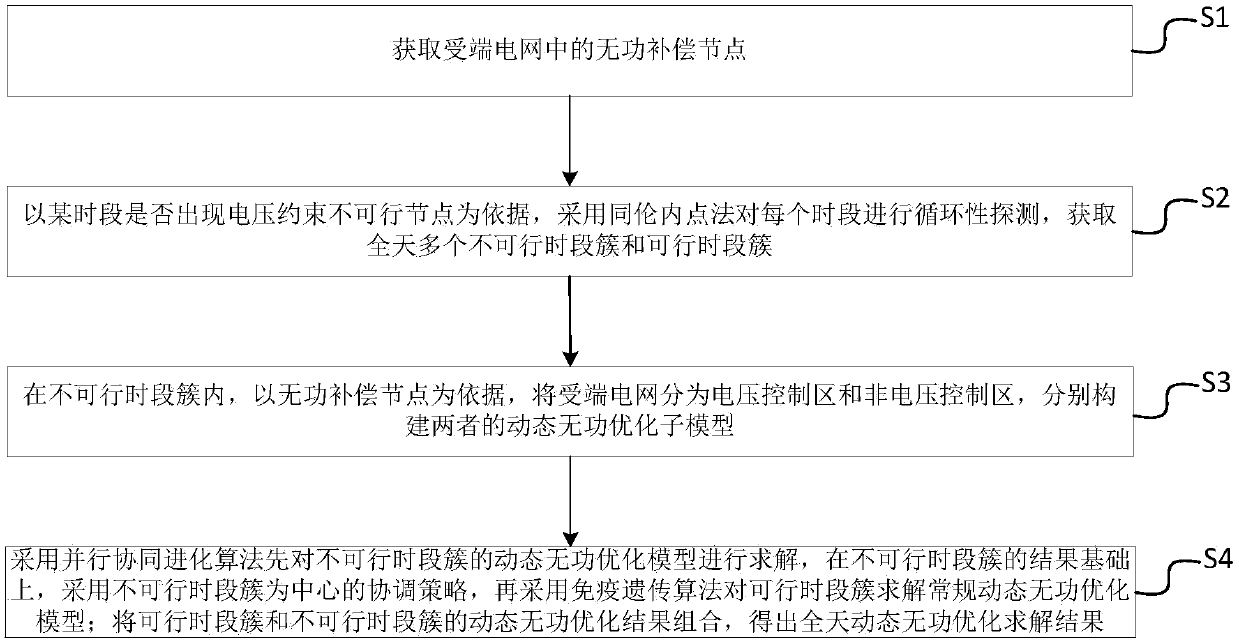
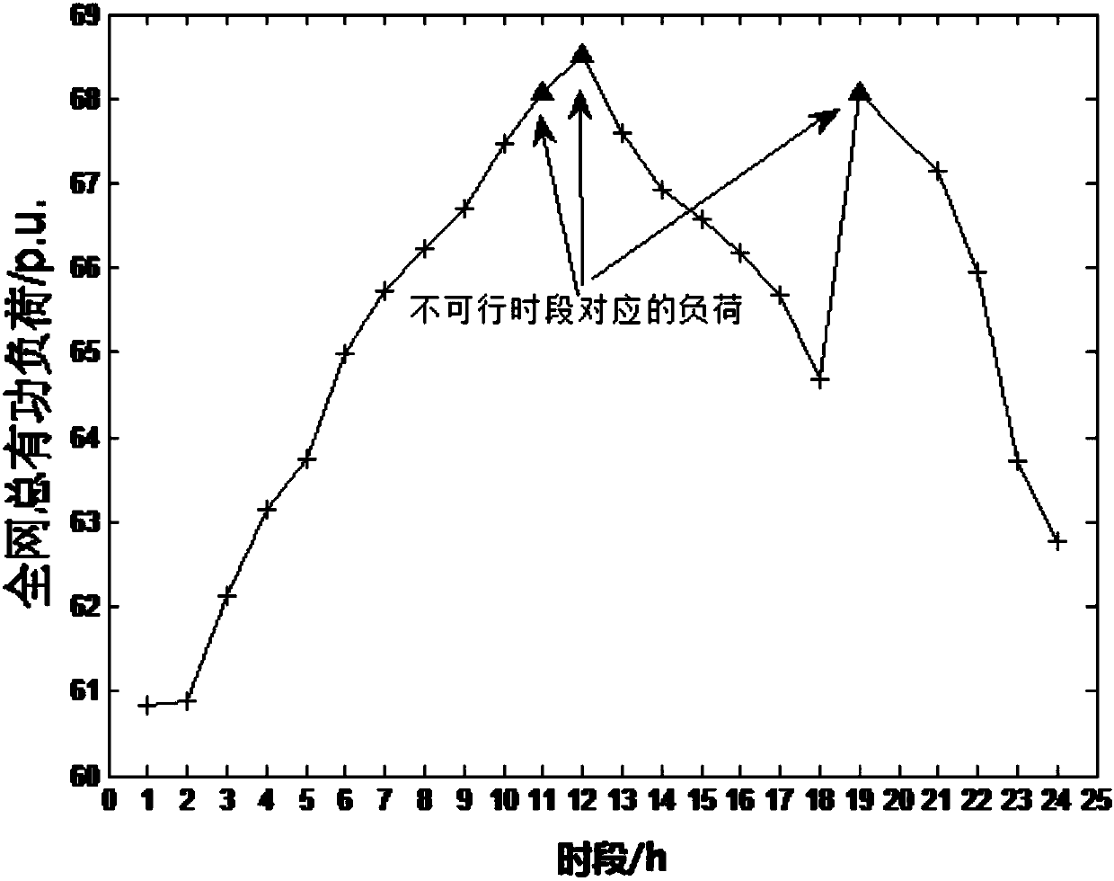
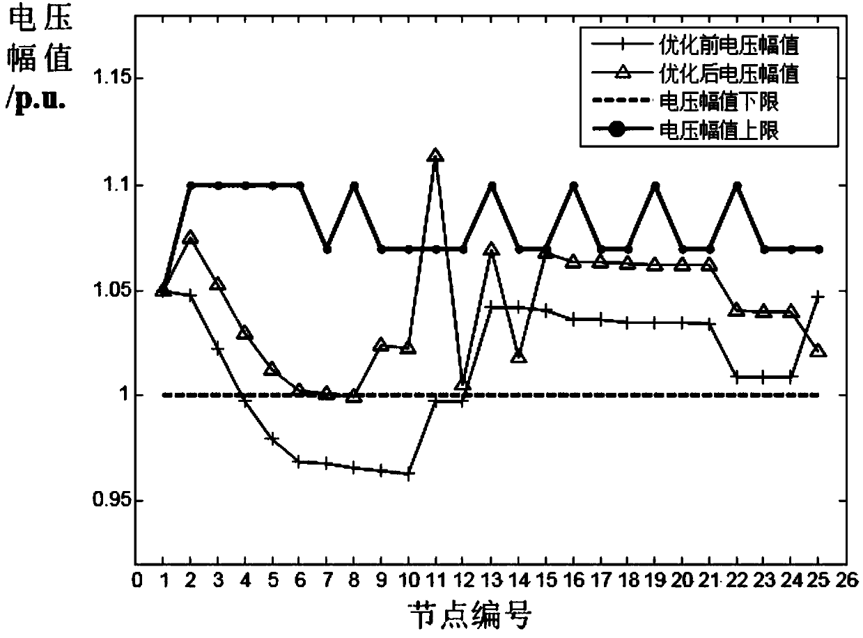
[0075] See Figure 1 to Figure 3 , this embodiment takes the 220kV and 110kV power grids as the grid, and connects to the 10kV load system as a specific embodiment to elaborate on the dynamic reactive power optimization method of the receiving end power grid containing voltage infeasible nodes in the present invention. Understandably, in other In the embodiment, the method of the present invention for the dynamic reactive power optimization method of the recei...


PUM


Abstract

The invention discloses a receiving-end power-grid dynamic reactive optimization method containing a voltage infeasible node and an apparatus thereof. The method comprises the following steps of S1, acquiring a reactive compensation node in a receiving-end power grid; S, taking a condition that whether a voltage constraint infeasible node is generated in one time period as a basis, carrying out circularity detection on each time period and acquiring a plurality of infeasible period clusters and feasible period clusters of a whole day; S3, in the infeasible period clusters, taking a reactive compensation node as a basis, dividing a receiving-end power grid into a voltage control area and a non-voltage control area and constructing dynamic reactive optimization submodels of the two areas respectively; S4, using a parallel coevolution algorithm to solve the dynamic reactive optimization submodel of the infeasible period clusters, based on a result of the infeasible period clusters, using a coordination strategy taking the infeasible period clusters as a center and then using an immune genetic algorithm to solve a conventional dynamic reactive optimization submodel for the feasible period clusters; and combining dynamic reactive optimization results of the feasible period clusters and the infeasible period clusters.

Description

technical field [0001] The invention relates to a method and device for dynamic reactive power optimization of a receiving-end power grid with voltage infeasible nodes. Background technique [0002] In large-scale urban receiving-end power grids, the main grid grids are 220kV and 110kV grids, and the main power point in the grid is a 500kV substation. The power grid in urban areas has a large scale and a relatively high power load density, and during the peak summer or winter peak season, the load of the entire network is running at a high level for a long time. In actual operation, the overload problem of the main transformer in 220kV and 110kV substations will cause the on-load voltage regulation of the main transformer to be locked. In addition, the maintenance of reactive power compensation capacitors at the 110kV station or insufficient configuration capacity will directly lead to the occurrence of 10kV buses in multiple 110kV substations. Low voltage problem, that is,...

Claims


Application Information

Patent Timeline
Patent Type & Authority Patents(China)
IPC IPC(8): H02J3/18
CPCH02J3/1871Y02E40/30
Inventor 王强钢周念成吴佳芳苏宇
Owner CHONGQING UNIV
Learn More