Power transmission and transformation line crystal cleaning device
A technology for cleaning devices and crystals, which is applied in the installation of cables, overhead installations, electrical components, etc. It can solve the problems of easily damaged power lines and unsatisfactory cutting effects, and achieve the effect of avoiding jamming or breaking and easy disassembly
- Summary
- Abstract
- Description
- Claims
- Application Information
AI Technical Summary
Problems solved by technology
Method used
Image
Examples
Embodiment 1
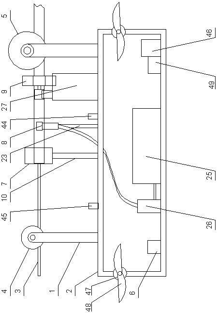
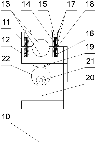
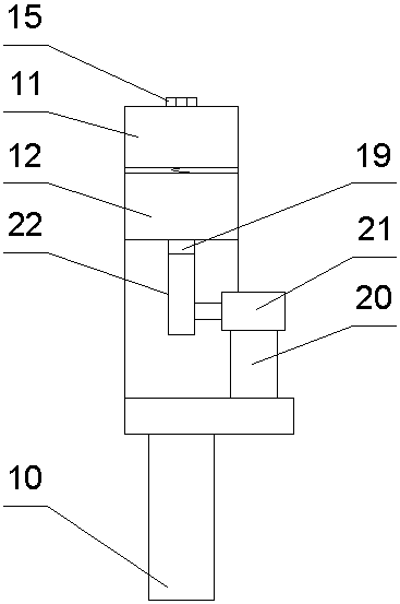
[0041] A device for clearing crystals of transmission and transformation lines, including a traveling mechanism and a frame 2 connected below the traveling mechanism through a mechanical arm 1, and the traveling mechanism includes a rear traveling mechanism that is stuck on the ice-coated part of the power line 3 The wheel 4 and the front running wheel 5 that are stuck on the ice-coated unremoved part on the power line 3 are provided with a deicing mechanism on the frame 2, and the deicing mechanism is located between the rear running wheel 4 and the front running wheel. 5, a wireless controller 6 is installed on the left side of the frame 2, and the running mechanism is connected to the wireless controller 6 by electrical signals; the deicing mechanism includes an ice-coated crushing module 7, Waterjet segmentation module 8 and pre-cutting module 9; the frame 2 is provided with a posture adjustment module 47 and a balance detection module 49 for posture adjustment.
[0042] T...
Embodiment 2
[0056] Such as Figure 8 As shown, the difference between it and Embodiment 1 is that: the top of the water tank 25 is provided with an opening, the opening is provided with a funnel 41 for receiving ice and snow, and the top of the frame 2 is provided with a gap corresponding to the position of the funnel 41 for receiving ice and snow 42 is used to install a heating module 43 at the bottom of the water tank 25 and the heating module 43 is electrically connected to the wireless controller 6 .
[0057]In this embodiment, an opening is set on the top of the water tank, and an ice and snow funnel is arranged on the opening, and a gap is provided at the top of the frame corresponding to the position of the ice and snow funnel to collect ice cubes falling from the power line, and the bottom of the water tank Set up a heating module and connect the heating module to the wireless controller with electrical signals, so that during the deicing process, some falling ice cubes can be col...
Embodiment 3
[0059] Such as Figure 9 As shown, the difference between it and Embodiment 2 is that: the center of gravity adjustment module is arranged at the bottom of the frame 2, and the center of gravity adjustment module includes a counterweight 47 that is slidingly arranged at the bottom of the frame 2 using a dovetail structure and is arranged on the bottom of the frame 2. The automatic telescopic rod 48 on the left side of the bottom of the frame 2, the free end of the automatic telescopic rod 48 is connected with the counterweight 47, and the automatic telescopic rod 48 is connected with the wireless controller 6 by electrical signals.
[0060] The automatic telescopic rod 48 is an electric telescopic rod.
[0061] In this embodiment, a center-of-gravity adjustment module is provided at the bottom of the frame to adjust the center of gravity of the device, so as to avoid the instability of the center of gravity from affecting the work of the device; The position of the block can ...
PUM
 Abstract
Description
Claims
Application Information
 - R&D
- Intellectual Property
- Life Sciences
- Materials
- Tech Scout
- Unparalleled Data Quality
- Higher Quality Content
- 60% Fewer Hallucinations
Browse by: Latest US Patents, China's latest patents, Technical Efficacy Thesaurus, Application Domain, Technology Topic, Popular Technical Reports.
© 2025 PatSnap. All rights reserved.Legal|Privacy policy|Modern Slavery Act Transparency Statement|Sitemap|About US| Contact US: help@patsnap.com


