
Charged particles emitting decay detection method and apparatus

A detection method and technology of charged particles, applied in measuring devices, radiation measurement, X/γ/cosmic radiation measurement, etc., can solve the problem of not fully exploring angle, time, position, energy information, etc., and achieve high image signal-to-noise Ratio, the effect of reducing background noise

Pending Publication Date: 2017-02-15
NANJING RAYCAN INFORMATION TECH
View PDF5 Cites 2 Cited by
  • Summary
  • Abstract
  • Description
  • Claims
  • Application Information

AI Technical Summary

Problems solved by technology

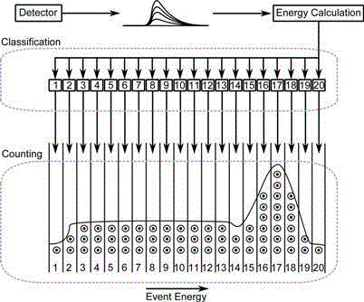
But the root cause is still not fully exploring the angle, time, position, and energy information of a single Cherenkov radiation event

Method used


Image

  • Charged particles emitting decay detection method and apparatus
  • Charged particles emitting decay detection method and apparatus
  • Charged particles emitting decay detection method and apparatus

Examples


example 1

[0058] The parameters for data processing in this embodiment are listed here:

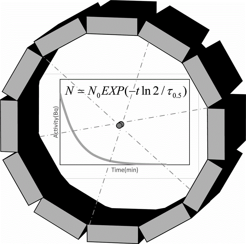
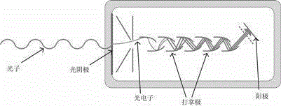
[0059] The actual device used in step (1) is to use a black box with a size of 1.8m×1.8m×1.8m and a positron annihilation gamma photon 18F-FDG with a radiation source of 511kev. The measured object is a cylindrical phantom filled with FDG. A position-sensitive photomultiplier tube with enhanced red light is used, and the detector adopts a ring structure;

[0060] Step (2) The coincidence time is about 8 ns, and the coincidence judgment adopts offline time-energy coincidence processing;

[0061] Step (3) using the analytical charged emission decay event reconstruction method to directly plot the time and location of the charged emission event;

[0062] Step (4) uses the analytical nuclide distribution reconstruction method to directly plot the time and position of Cherenkov.

example 2

[0064] The parameters for processing data in this application instance 2 are listed here:

[0065] The actual device used in step (1) is to use a black box with a size of 1.8m×1.8m×1.8m and a 124I-NaI radiation source of 511kev. The measured object is a rat filled with 124I-NaI. Red light enhanced silicon photomultiplier tube, the detector adopts a square composed of four flat plates;

[0066] Step (2) The coincidence time is about 10ns, and the coincidence judgment adopts the online time coincidence processing;

[0067] Step (3) adopts the iterative charged emission decay event reconstruction method, and draws the time and position of Cherenkov by approximation;

[0068] Step (4) The iterative nuclide distribution reconstruction method is used to approximate the time and position of the charged emission event, and iterate until the relative change rate is less than 1%.

[0069] The method and device of the present invention can be used in nuclear technology that radiates ch...


PUM


Abstract

Provided is a charged particles emitting decay detection method. The method includes obtaining pulse data sets (one or more of time, position, wavelength, pulse shape) of charged particles emitting Cherenkov effect photons; obtaining the pulse data sets (one or more of time, position, wavelength, pulse shape) of other particles emitted by means of decay; calculating the combined likelihood probability function for each time period sample; and determining whether the currently received data fragment is from a charged particles emitting event by calculating the combined multi-attribute likelihood function of the time period. A charged particles emitting decay detection method includes a Cherenkov detector module, an other-particle data detection module, a combined likelihood probability calculating module, and a decay event attribute selection module. The charged particles emitting decay event detection method and apparatus can effectively improve the device spatial resolution, energy resolution, time resolution, device sensitivity and imaging signal-to-noise ratio of the detected fired emission decay events, and are particularly suitable for the application of a tracer in high-energy physics and medical imaging.

Description

technical field [0001] The invention relates to the fields of digital signal processing, photoelectric signal processing and radiation detection, in particular to a detection method and device for charged emission decay. Background technique [0002] Charged Particles Emitting Decay is a decay event accompanied by the emission of charged particles. Since charged particles with a velocity greater than the phase velocity in the medium will radiate photons of visible light, near-infrared light, and soft ultraviolet light, this effect is called the Cerenkov effect, and the emitted photons are called Cerenkov photons. Radioactive isotopes with Cerenkov radiation can be used as probes for in vivo imaging. By participating in various physiological and biochemical processes of organisms, they can constitute a new imaging method. In optical imaging and multimodal medical imaging It has wide application value. In 2010, Alessandro Ruggiero et al. (J. Nucl. Med.2010,51:1123-1130) in t...

Claims


Application Information

Patent Timeline
Patent Type & Authority Applications(China)
IPC IPC(8): G01T1/00G01J11/00
Inventor 谢庆国邓贞宙
Owner NANJING RAYCAN INFORMATION TECH
Learn More