
Automobile pedal test method

A technology of automobile pedals, test methods, applied in the direction of vehicle testing, machine/structural component testing, measuring devices, etc.

Inactive Publication Date: 2017-02-15
TIANJIN RUIYITAIKE AUTO ELECTRONICS
View PDF0 Cites 5 Cited by
  • Summary
  • Abstract
  • Description
  • Claims
  • Application Information

AI Technical Summary

Problems solved by technology

[0003] The present invention provides a method for testing automobile pedals to solve the problem in the prior art mentioned in the above-mentioned background art that the measurement of each product cannot be realized by changing the type of tooling

Method used


Image

  • Automobile pedal test method
  • Automobile pedal test method

Examples


Embodiment

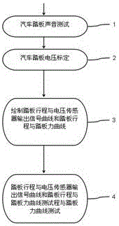
[0030] This embodiment: as figure 1 Shown, a kind of automobile pedal test method comprises automobile pedal sound test 1: judge whether to meet pedal spring sound output standard in pedal spring sound output test, if not meet, then cancel current test;

[0031] Car pedal voltage calibration 2: In the calibration point voltage output test, judge whether it meets the calibration point voltage output standard, if not, cancel the current test;

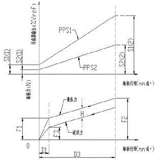
[0032] Draw pedal travel and voltage sensor output signal curves and pedal travel and pedal force curves 3: signal curve drawing;

[0033] Pedal stroke and voltage sensor output signal curve and pedal stroke and pedal force curve test 4:

[0034] According to the pedal stroke and voltage sensor output signal curve, determine whether the idle stroke point and dead point meet the corresponding standards, if not, cancel the current test;

[0035] According to the pedal stroke drawn by the signal curve and the output signal curve of the vol...


PUM


Abstract

The invention belongs to the technical field of automobile pedal testing and specifically relates to an automobile pedal test method which comprises the following steps: a step of automobile pedal sound testing, a step of automobile pedal voltage calibration, a step of drawing pedal travel and voltage transducer output signal curves, a step of drawing pedal travel and pedal force curves, a step of testing the pedal travel and voltage transducer output signal curves and a step of testing the pedal travel and pedal force curves; the automobile pedal test method helps solve a problem that each kind of products cannot be measured through tool changeovers via technologies of the prior art; beneficial technical effects of the automobile pedal test method are that whether an automobile pedal is good or poor in quality can be determined, a misjudgement rate caused by human intervention can be lowered, authenticity of traceability can be improved, and calibration accuracy can be increased.

Description

technical field [0001] The invention belongs to the technical field of automobile pedal testing, in particular to an automobile pedal testing method. Background technique [0002] The electronic accelerator pedal is used to input the user's control awareness of the accelerator to the ECU, and then the ECU controls the electronic throttle to control the accelerator. The electronic accelerator pedal has two built-in Hall effect chips, which convert the rotational movement of the pedal into a voltage signal and output it to the ECU, the output signal voltage of electronic accelerator pedal chip 1 is linearly proportional to the pedal angle, the output signal of chip 2 and chip 1 is in a translational or double relationship, and the output voltage signal is 0--5V. There are many types of electronic accelerator pedal products, and equipment needs to be considered For the compatibility of various products, the measurement of each product can be realized by changing the tooling. Th...

Claims


Application Information

Patent Timeline
IPC IPC(8): G01M17/007
CPCG01M17/007
Inventor 杨绍龙
Owner TIANJIN RUIYITAIKE AUTO ELECTRONICS
Learn More