In-orbit calibration method for high precision imaging moment

A technology of imaging time and correction method, applied in the field of high-precision satellite imaging, can solve the problems of complex algorithm, unfavorable implementation of on-board computer, low precision, etc., and achieve the effect of simple calculation

Active Publication Date: 2017-02-15
SHANGHAI AEROSPACE CONTROL TECH INST
View PDF3 Cites 2 Cited by
  • Summary
  • Abstract
  • Description
  • Claims
  • Application Information

AI Technical Summary

Problems solved by technology

At present, there is no method that can calculate the high-precision imaging time through optimization and correction measures from the aspect of on-board software design. The existing methods are not high in precision or have complex algorithms, which are not conducive to the realization of on-board computers.

Method used


Image

  • In-orbit calibration method for high precision imaging moment
  • In-orbit calibration method for high precision imaging moment
  • In-orbit calibration method for high precision imaging moment

Examples


Embodiment Construction

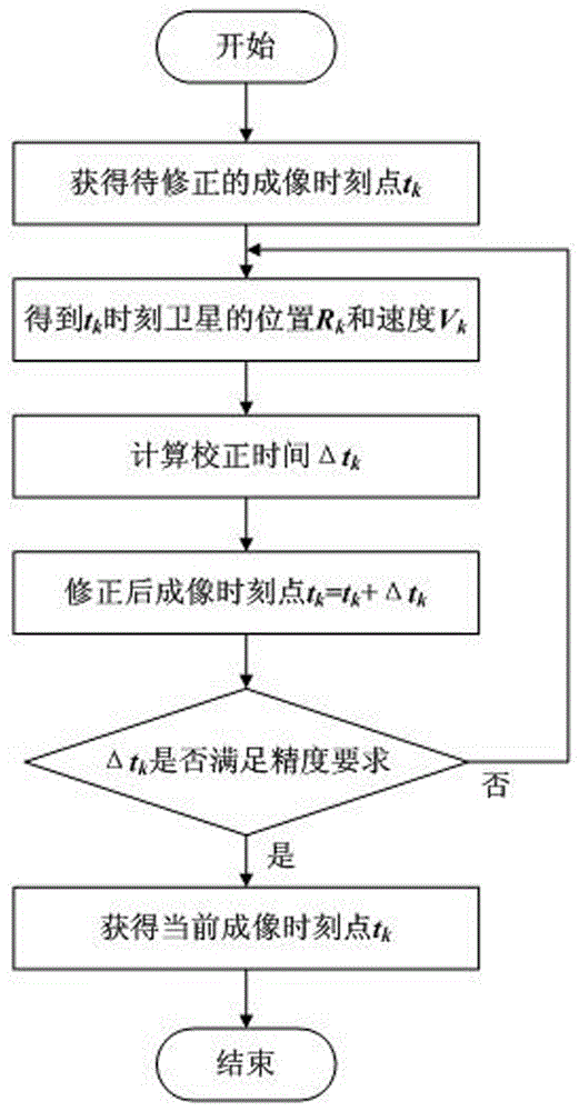
[0013] First introduce the relevant principles of the specific embodiments of the present invention below:

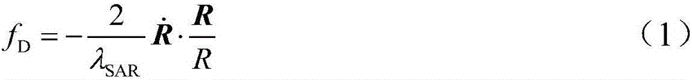
[0014] Doppler center frequency f D defined as

[0015]

[0016] Where: λ SAR is the working wavelength of the load; is the velocity vector of the satellite relative to the target point; R is the position vector of the satellite relative to the target point; R is the distance of the satellite relative to the target point.

[0017] in,

[0018] R=R s -R t (2)

[0019] Where: R s is the position vector of the satellite relative to the center of the earth; R t is the vector of the target point relative to the center of the earth.

[0020] After the two-dimensional guidance of the satellite in orbit, theoretically the Doppler frequency of the antenna center pointing to the relative imaging point is zero, that is, the best imaging point is that the relative position and velocity of the satellite and the target point are relatively vertical. Therefore, the purp...


PUM


Abstract

The invention provides an in-orbit calibration method for high precision imaging moment. The method comprises the following steps: step 1, acquiring the imaging moment sent from the ground on satellite; step 2, based on the acquired imaging moment, using the forecast satellite information from GPS receiver to acquire the satellite position and speed of the moment; step 3, based on the position and speed coordinated with the position of the imaging target point, calculating the calibrating the time deviation; step 4, calculating to obtain the calibrated imaging moment; step 5, judging whether the time deviation calibration meets the precision requirement. If not met, selecting the time acquired in step 4 to be the imaging moment, repeating the procedure from step 2 to step 5; if the requirement is met, the calibration calculation of imaging moment is completed, using the calibrated imaging moment to start the imaging device. The method has the advantages of low calculation burden and easy management for the satellite-borne computer. The method can be used for the determination of the high precision imaging moment during the normal working period of satellites, and provides a high precision time benchmark for the imaging.

Description

technical field [0001] The invention belongs to the technical field of satellite high-precision imaging, and in particular relates to a high-precision imaging time-on-orbit correction method. Background technique [0002] Nowadays, the imaging accuracy requirements of satellites are getting higher and higher, and the corresponding factors that affect the imaging accuracy need to be optimized to minimize the error. One of the factors affecting the imaging accuracy is the precise determination of the imaging moment. [0003] According to the ground plan of the satellite mission, the geographic latitude and longitude of the imaging target point and the corresponding imaging startup time t will be uploaded within multiple days k . Due to the ground orbit recursion error, there may be some errors in the optimal start-up time for imaging corresponding to the imaging target point, and it is necessary to correct the start-up time on the satellite in order to expect the best observ...

Claims


Application Information

Patent Timeline
Patent Type & Authority Applications(China)
IPC IPC(8): G01C25/00
CPCG01C25/00
Inventor 范季夏王文妍何益康吴敬玉王新
Owner SHANGHAI AEROSPACE CONTROL TECH INST
Why Eureka
Try Eureka