
Ceramic tile sintering device

A sintering device and ceramic tile technology, applied in the furnace type, furnace, charge composition/state, etc., can solve the problems of the difference in the color of the tiles and the inability to heat the tiles uniformly, and achieve the effects of uniform heating, low color difference and uniform heat.

Inactive Publication Date: 2017-02-15
绥阳县华夏陶瓷有限责任公司
View PDF5 Cites 0 Cited by
  • Summary
  • Abstract
  • Description
  • Claims
  • Application Information

AI Technical Summary

Problems solved by technology

[0005] The present invention intends to provide a tile sintering device to solve the problem that the existing sintering mechanism cannot uniformly heat the tiles, resulting in differences in the color of the tiles

Method used


Image

  • Ceramic tile sintering device
  • Ceramic tile sintering device

Examples


Embodiment Construction

[0019] The present invention will be described in further detail below by means of specific embodiments:

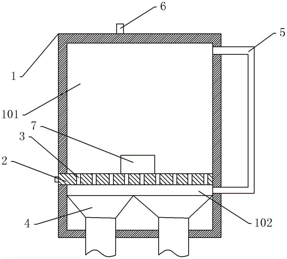
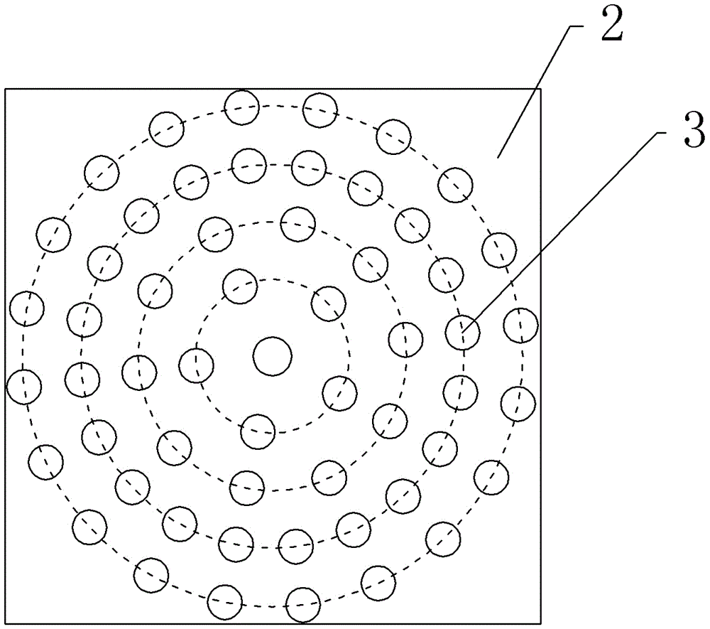
[0020] The reference numerals in the accompanying drawings of the description include: firing box 1, heating chamber 101, air flow chamber 102, drawing plate 2, through hole 3, spray gun 4, return pipe 5, pressure relief valve 6, ceramic tile 7.

[0021] Such as figure 1 As shown, a ceramic tile sintering device includes a firing box 1, a spray gun 4 and a return pipe 5. The top of the firing box 1 is provided with a pressure relief valve 6, and the bottom of the firing box 1 is provided with a drawer plate 2. A sealing ring is provided on the contact surface between the plate 2 and the firing box 1. The drawing plate 2 divides the firing box 1 into a heating chamber 101 and an air flow chamber 102. The heating chamber 101 is located above the drawing plate 2, and the air flow chamber 102 is located on the Below the drawing plate 2; as figure 2 As shown, there are seve...


PUM


Abstract

The invention belongs to the field of ceramic tile production and discloses a ceramic tile sintering device. The ceramic tile sintering device comprises a sintering box, spray guns and a return pipe. A drawing and pulling plate is arranged on the bottom of the sintering box, a plurality of through holes are formed in the drawing and pulling plate, the drawing and pulling plate divides the sintering box into an air flow cavity and a heating cavity, the heating cavity is located above the drawing and pulling plate, and the air flow cavity is located below the drawing and pulling plate. The spray guns are arranged in the air flow cavity. The air flow cavity communicates with the heating cavity through the return pipe. By means of the scheme, ceramic tiles are heated more evenly, and therefore the sintered ceramic tiles are low in color difference.

Description

technical field [0001] The invention belongs to the field of ceramic tile production, and in particular relates to a ceramic tile sintering device. Background technique [0002] Ceramic tile is an indispensable decorative material; in the production process of ceramic tile, the sintering temperature and sintering time in the kiln will have a great impact on the performance of the product when the tile is sintered. The current ceramic tile sintering structure adopts single gun sintering, which causes uneven heating of the middle part and both sides of the tile during sintering, resulting in inconsistent fineness of the sintered tiles. [0003] The Chinese patent document with the publication number CN203464716U discloses a ceramic brick sintering device with an improved structure, including adobe brick transmission mechanism, multi-gun sintering mechanism, fired product transmission mechanism and control equipment. The high-temperature sintering of the multi-gun sintering mec...

Claims


Application Information

Patent Timeline
Patent Type & Authority Applications(China)
IPC IPC(8): F27B21/00F27B21/08F27D7/02
CPCF27B21/00F27D7/02F27M2001/1517F27M2003/04
Inventor 王麟华
Owner 绥阳县华夏陶瓷有限责任公司
Learn More