a buffer mechanism

A buffer mechanism and cavity technology, applied in the field of buffer mechanisms, can solve problems such as reducing maintenance of the buffer mechanism, and achieve the effects of eliminating friction, reducing the entry of dust, and avoiding contact

Active Publication Date: 2018-09-11
嘉善申乐五金塑料有限公司
View PDF6 Cites 0 Cited by
  • Summary
  • Abstract
  • Description
  • Claims
  • Application Information

AI Technical Summary

Problems solved by technology

[0002] In industrial production, many mechanical equipment are inseparable from buffering. Buffering can not only weaken the large direct impact force, but also provide protection for the equipment to avoid excessive or frequent impacts causing damage to the equipment; in the commonly used buffer mechanism The hydraulic cylinder and the bearing are connected together to realize the buffer mechanism, but the bearing needs to add lubricating oil frequently, and the hydraulic cylinder also needs to be maintained frequently. If there is any problem, the equipment may break down and stop running. Therefore, it is necessary to design a A buffer mechanism that does not require bearings and hydraulic pressure, avoids the use of lubrication, and reduces maintenance.

Method used


Image

  • a buffer mechanism
  • a buffer mechanism

Examples


Embodiment Construction

[0018] In order to make the technical means, creative features, goals and effects achieved by the present invention easy to understand, the present invention will be further elaborated below in conjunction with illustrations and specific embodiments.

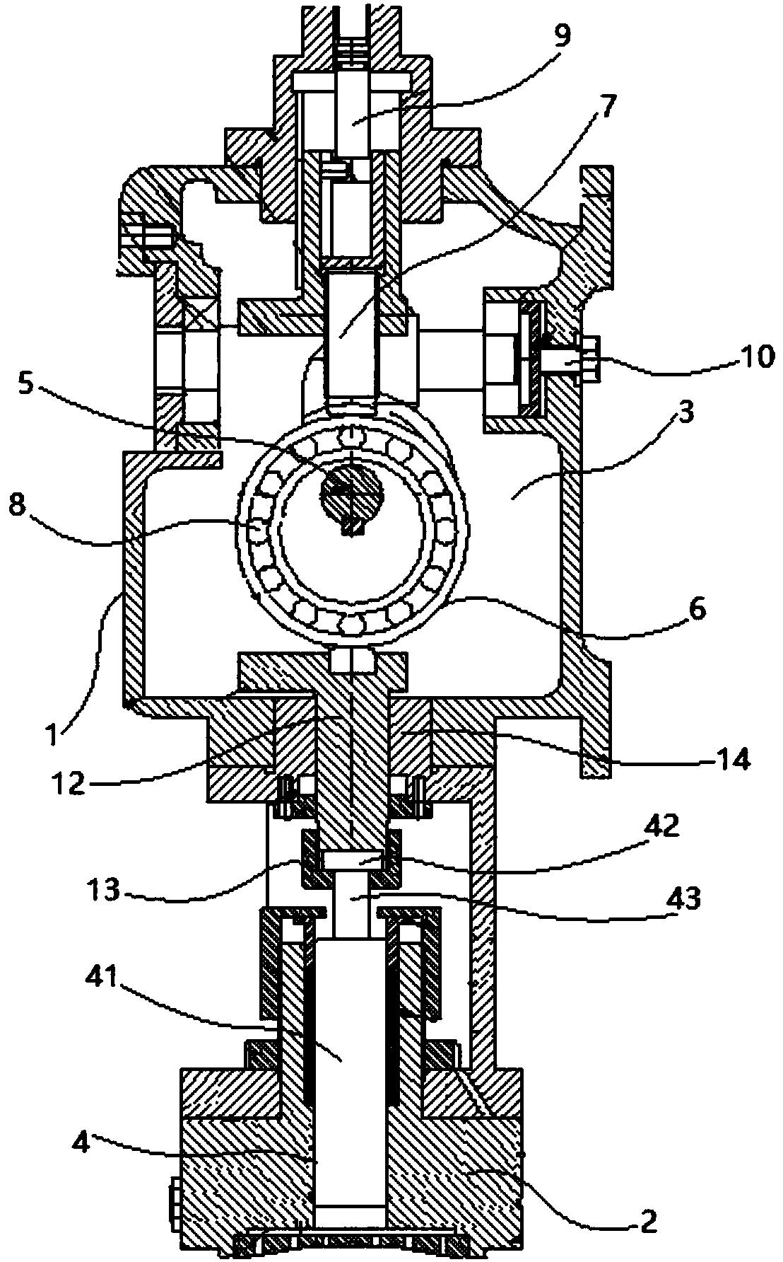
[0019] refer to figure 1 , figure 2 As shown, this buffer mechanism includes a cavity 1, a base 2 is provided at the lower end of the cavity 1, an inner cavity 3 is arranged in the cavity 1, and a Pneumatic system 4, a main shaft 5, an eccentric wheel 6 and a shaft rod 7 are also arranged in the cavity 1, the eccentric wheel 6 is installed on the main shaft 5, an inner wheel and an outer wheel are arranged on the eccentric wheel 6, and an inner wheel and an outer wheel are arranged between the inner wheel and the outer wheel The roller 8 is evenly arranged between the inner wheel and the outer wheel of the eccentric wheel 6;

[0020] A shaft 7 is arranged above the eccentric wheel 6, the lower end of the shaft 7 is connected ...


PUM


Abstract

The invention discloses a buffer mechanism which comprises a cavity; a base is arranged at the lower end of the cavity; an inner cavity is formed in the cavity; a pneumatic system is arranged between the inner cavity and the base; the cavity is also internally provided with a spindle, an eccentric wheel and a shaft rod; the eccentric wheel is installed on the spindle and is provided with an inner wheel and an outer wheel; and rolling wheels are uniformly arranged between the inner wheel of the eccentric wheel and the outer wheel of the eccentric wheel. According to the buffer mechanism, the eccentric wheel is arranged in the inner cavity and installed on the spindle, the shaft rod in the inner cavity pushes the spindle to move downward, the eccentric wheel rotates and slowly presses a piston downward driven by movement of the spindle, in addition, the piston is installed on a gas bearing, and a gas die is formed between the piston and a cylinder barrel by combining the piston and the gas bearing together, thus enough strong pressure is generated to enable the piston and the cylinder barrel to be prevented from contacting, friction of a cylinder is lowered and even eliminated, smooth buffer and shock absorption actions are realized, and the service life is prolonged.

Description

technical field [0001] The invention relates to the field of machining production, in particular to a buffer mechanism. Background technique [0002] In industrial production, many mechanical equipment are inseparable from buffering. Buffering can not only weaken the large direct impact force, but also provide protection for the equipment to avoid excessive or frequent impacts causing damage to the equipment; in the commonly used buffer mechanism The hydraulic cylinder and the bearing are connected together to realize the buffer mechanism, but the bearing needs to add lubricating oil frequently, and the hydraulic cylinder also needs to be maintained frequently. If there is any problem, the equipment may break down and stop running. Therefore, it is necessary to design a A buffer mechanism that does not require bearings and hydraulic pressure, avoids the use of lubrication, and reduces maintenance. [0003] The present invention is the improvement carried out in order to sol...

Claims


Application Information

Patent Timeline
Patent Type & Authority Patents(China)
IPC IPC(8): F16F9/18
CPCF16F9/18
Inventor 李栋
Owner 嘉善申乐五金塑料有限公司
Why Eureka
Try Eureka