
Improved clamping structure for vehicle steering pipe string

A steering column and automobile technology, applied to the steering column and the steering control installed on the car, etc., can solve the problems such as the large adjustment force of the steering column, the inability to ensure the lock of the handle, and the inability to completely separate the rack, etc., to achieve Low processing cost, avoid tooth-to-tooth phenomenon, and simple structure

Active Publication Date: 2017-02-15
BOSCH HUAYU STEERING SYST CO LTD
View PDF5 Cites 0 Cited by
  • Summary
  • Abstract
  • Description
  • Claims
  • Application Information

AI Technical Summary

Problems solved by technology

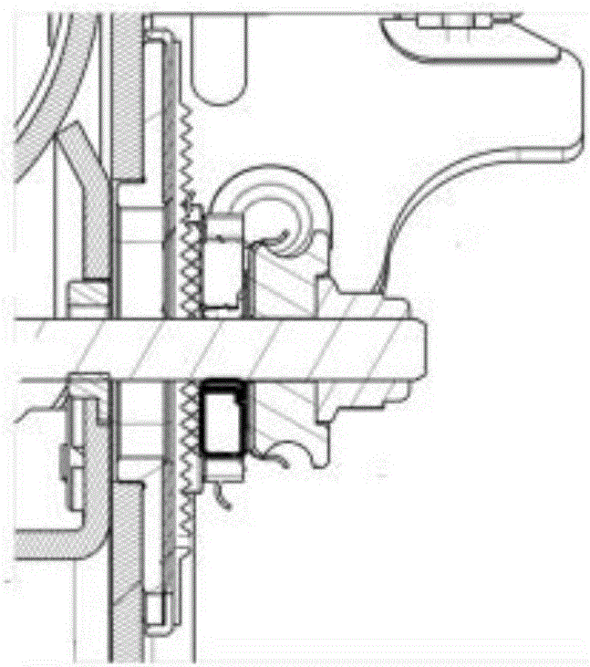
However, the rack structure will produce the following two problems: first, tooth to tooth, when the rack is in a state of incomplete meshing, such as figure 1 As shown, the handle cannot be locked at this position, that is, it cannot be guaranteed that the handle can be locked at any position. The operator needs to manually adjust each time until the rack is fully engaged to lock the handle; second, when the handle is released, the engaged rack If they cannot be completely separated, the adjustment force of the steering column will become larger, the adjustment will not be smooth, and the adjustment noise will be generated.

Method used


Image

  • Improved clamping structure for vehicle steering pipe string
  • Improved clamping structure for vehicle steering pipe string

Examples


Embodiment Construction

[0015] The present invention will be further described in conjunction with the accompanying drawings.

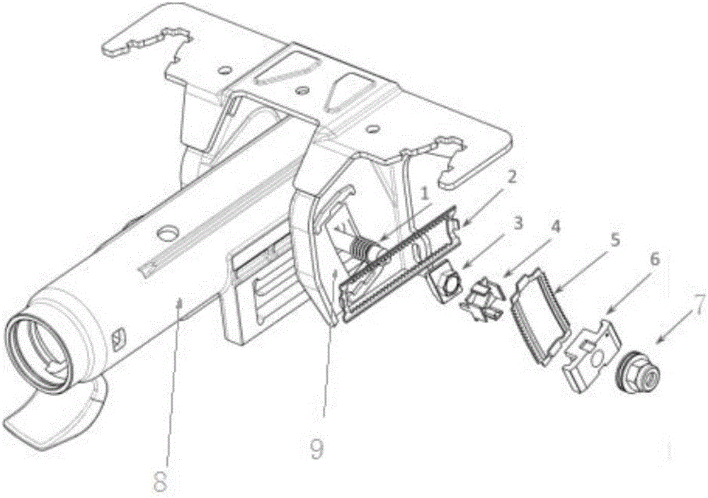
[0016] see figure 2 , the present invention designs an improved automobile steering column clamping structure, comprising: an upper column 8, a U-shaped frame 9, a handle spring 1, the outer side of the upper column 8 is provided with a U-shaped frame 9, and the handle The spring 1 penetrates the upper pipe column 8 and the U-shaped frame 9 from one side of the upper pipe column 8, and the penetrating end of the handle spring 1 is provided with an axial spring rack 2, and a shaft is fixed in front of the axial spring rack 2. To the rack 3, the front of the axial rack 3 is provided with a right radial soft limiter 4, the right radial soft limiter 4 is provided with a radial spring rack 5, and the radial spring rack 5 is clamped with a The radial rack 6 is provided with a tightening nut 7 in front of the radial rack 6; the two ends of the radial spring rack 5 and the U-shape...


PUM


Abstract

The invention relates to the technical field of automotive component manufacturing, in particular to an improved clamping structure for a vehicle steering pipe string. The improved clamping structure for the vehicle steering pipe string comprises an upper pipe string, a U-shaped frame and a handle spring, wherein the U-shaped frame is arranged in a sleeving manner outside the upper pipe string, and the handle spring penetrates the upper pipe string and the U-shaped frame from one side of the upper pipe string; an axial spring rack is arranged at the penetrating end of the handle spring in a sleeving manner, and an axial rack is fixed in front of the axial spring rack; a right radial soft retainer is arranged in front of the axial rack, a radial spring rack is arranged on the right radial soft retainer in a sleeving manner, a radial rack is arranged on the radial spring rack in a sticking manner, and a tightening nut is arranged in front of the radial rack; and both ends of the radial spring rack and the U-shaped frame are fixed by a laser welding manner. According to the improved clamping structure disclosed by the invention, the axial spring rack and the radial spring rack are adopted, so that when a handle is locked, the occurrence of a tooth-to-tooth phenomenon is avoided and deformation potential is accumulated at the same time because of deformability of the spring; and when the handle is released, the deformation potential is released and the engaged racks are bounced off, so that a driver can achieve a smooth adjustment. The improved clamping structure disclosed by the invention is simple in structure, practical, convenient, and low in processing cost.

Description

technical field [0001] The invention relates to the technical field of automobile parts manufacturing, in particular to an improved automobile steering column clamping structure. Background technique [0002] The steering column of automobiles often adopts a rack meshing structure to improve the holding force of the steering column, and the rack structure has the advantages of good economy. However, the rack structure will produce the following two problems: first, tooth to tooth, when the rack is in a state of incomplete meshing, such as figure 1 As shown, the handle cannot be locked at this position, that is, it cannot be guaranteed that the handle can be locked at any position. The operator needs to manually adjust each time until the rack is fully engaged to lock the handle; second, when the handle is released, the engaged rack If it cannot be completely separated, the adjustment force of the steering column will become larger, the adjustment will not be smooth, and the...

Claims


Application Information

Patent Timeline
IPC IPC(8): B62D1/18
CPCB62D1/18
Inventor 陈海明魏宇翔胡桃华汪兵兵孙舒婷
Owner BOSCH HUAYU STEERING SYST CO LTD
Learn More